FOCKE MELER GLUING SOLUTIONS
3-10
INSTALLATION
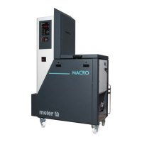
3. Remove the connector from the card and connect the two cable wires
to their corresponding connector terminals:
1 common + voltage output
2 input for inhibitor output 1
3 input for inhibitor output 2
4 input for inhibitor output 3
5 input for inhibitor output 4
6 input for inhibitor output 5
7 input for inhibitor output 6
8 without connection.
4. Reconnect the card connector.
5. Make sure that the cable is well connected and that its path through
the electrical cabinet presents no risks of snagging, being cut or any
other accidental deterioration.
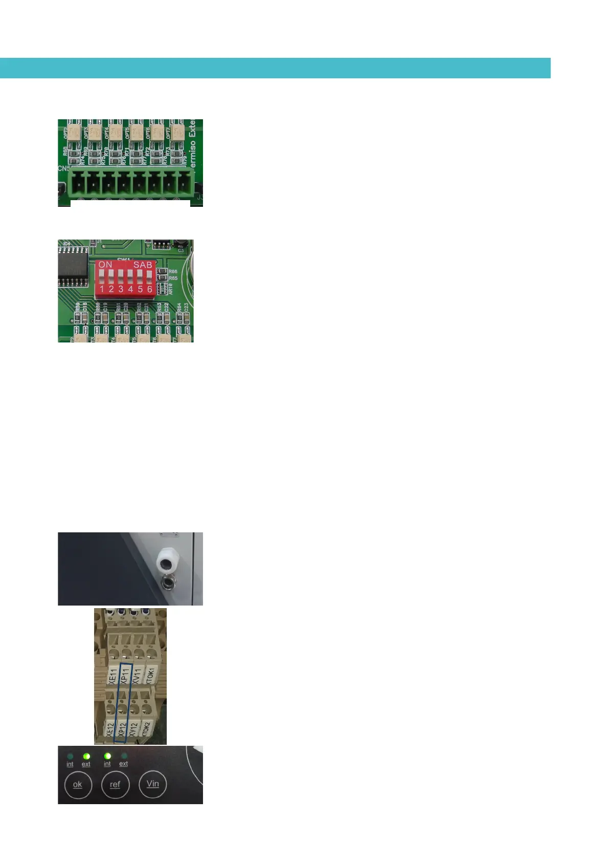
It is possible to select the channels that you want to control from the outside
using the small switches located above the connecter. Switches 1 through 6
control each of the channels, so that the switch in the ‘ON’ position means
heating from the equipment, without any external control.
When the switch is in the ‘OFF’ position, the corresponding channel does not
heat unless activated from the outside, through a non-voltage contact between
pin 1 (the common pin) and the pin that corresponds to the channel.
Starting up the motor (ok ext)
1. If this is the only signal being connected, use 0.5 mm
2
two-wire cable.
2. Thread the power cord (max. Ø12.5 mm) through the electrical wall
bushing Pg13 and fasten it to the inside anchor, making sure that the
cord reaches the power card connector.
3. Connect the two wires from the start-up signal to the terminals XP11
and XP12. This is a double terminal, which makes it necessary to
connect each wire in one of the two holes in the terminal. Since this
contact is not under voltage, there is no connection polarity.
4. Make sure that the cables are firmly attached by the terminal screws.
5. For the signal to work, the led ‘ok ext’ on the control panel must be on.
1 2 3 4 5 6 7 8