PNEUMATIC DIAGRAMS
8-1
MA-5052-ENG MACRO SERIES MELTER MANUAL
8. PNEUMATIC DIAGRAMS
Components list
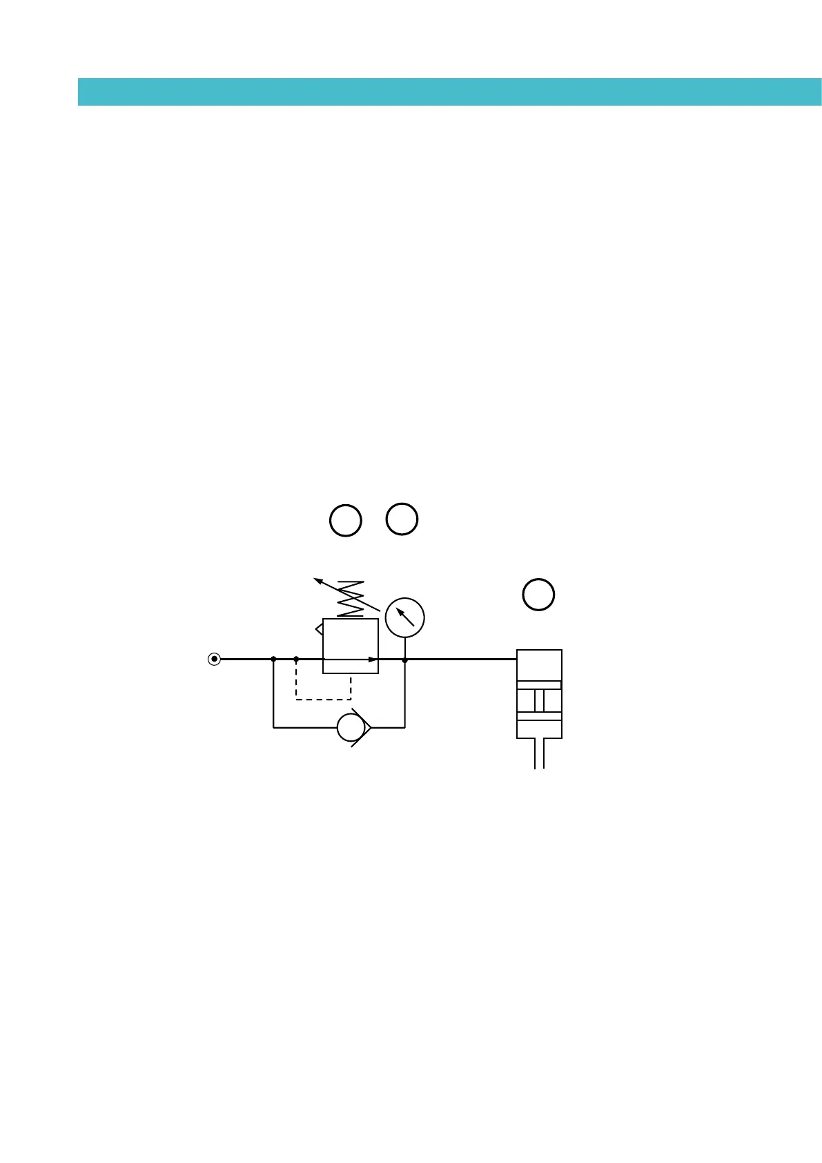
Pneumatic by-pass valve control system (optional)
- 1 Pressure regulator 1-10 bar.
- 2 Pressure gauge 0-10 bar.
- 3 Pneumatic limit control valve.
ENTRADA AIRE
AIR INPUT
VÁLVULA LIMITADORA / PRESSURE LIMIT VALVE
RELACIÓN / RATIO 1:15
3
1
2
MANÓMETRO
MANOMETER
P: 0-10 bar
REGULADOR DE PRESIÓN
PRESSURE REGULATOR
P: 0-10 bar