INSTALLATION
3-9
MA-5052-ENG MACRO SERIES MELTER MANUAL
contact NO
contact NO
4. Reconnect the card connector.
5. Make sure that the cable is well connected and that its path through
the electrical cabinet presents no risks of snagging, being cut or any
other accidental deterioration.
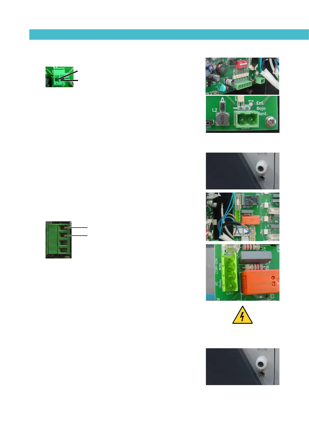
Low level (optional)
1. If this is the only signal being connected, use 0.5 mm
2
two-wire cable.
2. Open the electrical cabinet door as far as possible. Thread the power
cord (Ø4-8 mm) through the wall bushing Pg13 and fasten it to the
inside anchor, making sure that the cord reaches the power card
connector at the position where it will be installed.
3. Remove the connector from the card and connect the two cable wires
to their corresponding connector terminals:
1 contact NO
2 contact NO
4. Reconnect the card connector.
5. Make sure that the cable is well connected and that its path through
the electrical cabinet presents no risks of snagging, being cut or any
other accidental deterioration.
Warning: It must be connected to 24 AC or DC voltage. If you connect this
signal to 230V load current cannot be less than 50mA.
Output inhibitor
1. If this is the only signal being connected, use a seven-wire cable no
smaller than 0.22 mm
2
.
2. Open the door to the electrical cabinet as far as possible. Thread the
power cord (Ø4-8 mm) through the electrical wall bushing Pg13 and
fasten it to the inside anchor, making sure that the cord reaches the
power card connector at the position where it will be installed.
1
2
1
2