Pneumatic Module
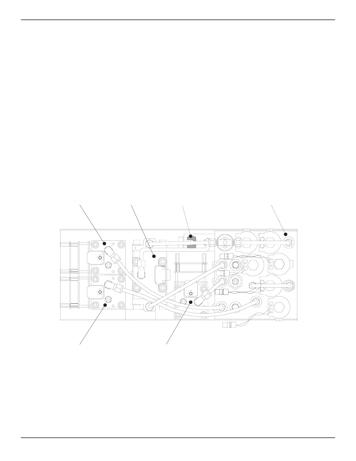
The pneumatic module (figure 1.4) includes a pri-
mary Silicon Pressure Transducer (SPT) consist-
ing of a sensor inside a rugged aluminum housing,
and three piggy-backed circuit board assemblies
mounted to the outside. These boards contain the
signal conditioning and calibration constants for
the SPT. The pneumatic module also includes a
Reed Valve Regulator (RVR) pressure controller, an
auxiliary transducer, a manifold, and all of the
interconnecting plumbing. The pneumatic module
also has the cables required to connect it to the
electrical module. In addition, this module may
include as options, one or two additional
transducers (3 SPTs maximum), shown at address
#01 and #02.
The electrical and pneumatic modules are each
self-contained and can be replaced individually.
System accuracy is maintained when any compo-
nent is replaced because the transducer’s calibra-
tion data resides on the transducers.
The only moving parts in the PCS 400 are the fan,
the disk drive mechanism, the pneumatic flow
controller diaphragms and valves, and the solenoid
valve plungers. There are no internal user adjust-
ments or setup switches.
Shown configured with three SPTs (maximum)
Manifold
Regulator
Auxiliary
Transducer
L1
L2
L3
L4
L5
L6
PT #01
Secondary
(Optional)
SPT #02
Baro Ref
O
tional
SPT #00
(Primary)
Figure 1.4 - Top View of Pneumatic Module
PCS 400 INTRODUCTION
www.mensor.com 1-3