CALIBRATING A GAUGE PRESSURE
INSTRUMENT
With the PCS 400 and any remote transducers
connected to the Gauge Calibration Setup, vent the
pressure to atmosphere, and set the instrument to
the MEASURE mode.
The current calibration of the active sensor can
now be checked at a number of pressure points
from zero to full scale. If recalibration is needed,
proceed with the following.
Calibrating the A/D
After the warmup and before the zero and span are
calibrated, the Analog to Digital converters on the
active transducer should be recalibrated. This is
done from the keypad by pushing [2nd], [CAL], [+],
[+], and on the ‘CAL A/D’ prompt, push [=] to
automatically recalibrate the A/D zero and span. If
the PCS 400 beeps and does not return the pass-
word prompt, then the A/D has been re-calibrated.
Press [CE] to return to the prior mode.
The A/D can be calibrated over the GPIB by sending
‘_PCS4 CAL A/D digits‘, where digits is the number
of the active transducer.
Setting the Sensor Zero
With the instrument in the VENT mode and the
pressure vented to atmosphere, from the keypad
push: [2nd], [CAL], [=] enter password [=] [=]. At
the SENSOR ZERO prompt, type in the true differ-
ential pressure, [0], and [=] to enter the reading
into memory. Press [CE]. The display should now
indicate the zero pressure reading.
To set zero over the GPIB, send the command
‘_PCS4 CAL ZERO value‘, where value is the true
pressure, (0).
NOTE: The zero adjustment can be used
as a tare offset by adjusting the display
to the required tare value. The maximum
zero offset is approximately ± 16 psi.
Setting the Sensor Span
Close the vent and apply a known pressure equal
to or near the span of the sensor.
From the keypad, push [2nd], [CAL], [+], [=] enter
password [=] [=]. At the SENSOR SPAN prompt,
type in the true pressure and then [=] to enter the
reading. The range of span adjustment available is
± 0.1% of the transducer full scale value. Press
[CE]. The display should now indicate the new true
pressure.
From the GPIB, send the command ‘_PCS4 CAL
SPAN value‘, where value is the true pressure
applied to the sensor. The recalibration is now
complete.
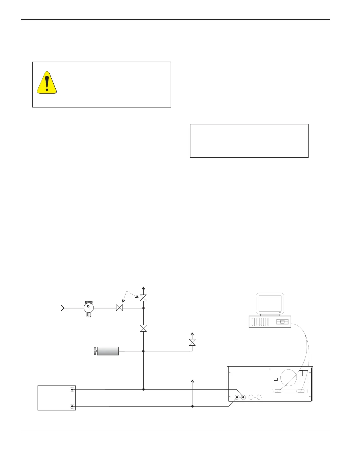
PRESSURE
REFERENCE
ATMOSPHERE
SHUT-OFF
VAL VE
VOLUME
CONTROLLER
VENT
LINE
REGULATOR
SHUT-OFF
VALVES
METERING
VAL VE
PRESS
REF
PRESSURE
STANDARD
(DWT)
PRESSURE
SUPPLY
IEEE STD 488 PORT
SH1, AH1, T6, L4,
SR1, RL1, PPO,
DC1, DT1, E2, C0
PCS 400
MEASURE/
CONTROL
REFERENCE
EXHAUST SUPPLY
SERIAL PORT
FUSE: 250V/1.5A
“This equipment complies withthe requirements in Part 15
of FCC Rules for a Class A com puting device. Operation of
this equipment in a residential area may cause
unacceptable interference to radio and TV reception
requiring the operator to take whateve r steps are necessary
to correct the interference.”
GPIB or
RS-232
COMPUTER
(OPTIONAL)
Figure 6.1 - Calibration Setup for Gauge Pressure
WARNING: POSSIBLE INJURY!
The tubing, valves and other apparatus
attached to the gauge must be adequate
for the maximum pressure which will
be applied, otherwise physical injury to
the operator or bystanders is possible.
CALIBRATION PCS 400
6-2 www.mensor.com