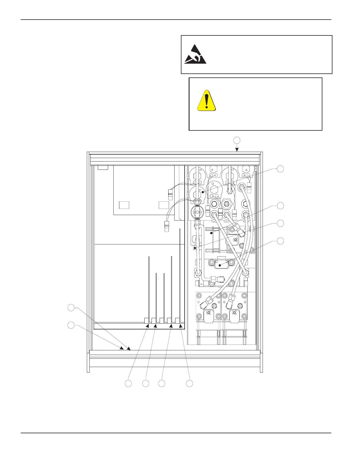
TROUBLESHOOTING GUIDE
The following information was developed from our
experience at the factory in producing and servicing
the PCS 400. It is provided to assist the user in
locating the cause of symptoms that might be en-
countered and corrected on site. The circled num-
bers in the table below refer to the key numbers in
figure 5.1, which are used to indicate approximate
locations.
NOTE: Figure 5.1 reflects the current configura-
tion for a standard PCS 400 with two pressure
channels plus a Barometric Reference Transducer.
Older units and other options may be configured
differently.
CAUTION: ESD PROTECTION REQUIRED.
The proper use of grounded work surfaces and
personal wrist straps are required when coming
into contact with exposed circuits (printed circuit
boards) to prevent static discharge damage to
sensitive electronic components.
Front
NOTES:
1. The plug-in boards may be arranged in a different order than illustrated.
2. The CMOS Battery is located on the CPU Board in some systems.
Rear
876 5
12
1
2
3
10
4
9
CPU BOARD
GPIB
PRINTER DRIVER
SOLENOID DRIVER
PL
A
Figure 5.1 - Chassis Assembly-Top View
CAUTION: PREVENT POWER
SURGES! Shut off power to the
PCS 400 before connecting or
disconnecting circuit boards and
connectors. With system power
on the voltage spikes generated by
such activity can damage sensitive
electronic components.
MAINTENANCE PCS 400
5-2 www.mensor.com