CALIBRATING AN ABSOLUTE
PRESSURE INSTRUMENT
With the PCS 400 and any remote transducers
connected to the Absolute Calibration Setup, close
the vent and connect the vacuum pump to the
MEASURE/CONTROL port. Set the instrument to
the MEASURE mode.
Evacuate the transducer to a low pressure that will
still maintain a viscous flow. This can be achieved
at a pressure ≥ 40 pascal (300 millitorr). (At pres-
sures lower than this the actual pressure at any
particular point in the system is questionable.)
Allow from five to ten minutes for the target pres-
sure to stabilize, then convert the pascal reading to
an equivalent instrument reading for the active
measurement units. Pascal conversion factors are
provided in table 9.3 in the Appendix.
The current calibration of the active sensor can
now be checked at a number of pressure points
from zero to full scale. If recalibration is needed,
proceed with the following.
Calibrating the A/D
After the warmup and before the zero and span are
calibrated, the Analog to Digital converters on the
active transducer should be recalibrated. This is
done from the keypad by pushing [2nd], [CAL], [+],
[+], and on the ‘CAL A/D’ prompt, push [=] to
automatically recalibrate the A/D zero and span. If
the PCS 400 beeps and does not return the pass-
word prompt, then the A/D has been re-calibrated.
Press [CE] to return to the prior mode.
The A/D can be calibrated over the GPIB by sending
‘_PCS4 CAL A/D digits‘, where digits is the number
of the active transducer.
Setting the Sensor Zero
With the instrument in the MEASURE mode and
the pressure ≥ 40 pascal (300 millitorr), convert
the pascal reading into the current displayed engi-
neering units. From the keypad push: [2nd], [CAL],
[=] enter password [=] [=]. At the SENSOR OFF-
SET prompt, type in the true absolute pressure,
[XXX], and [=] to enter the reading into memory.
Press [CE]. The display should now indicate the
current “zero” pressure reading.
To set zero over the GPIB, send the command
‘_PCS4 CAL ZERO value‘, where value is the true
pressure, (XXX).
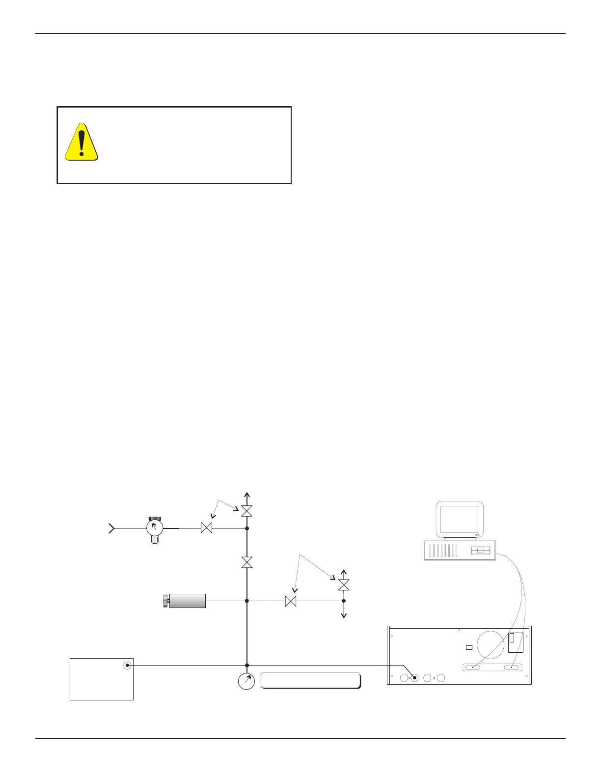
PRESS
PRESSURE
STANDARD
(DWT)
VACUUM
PRESSURE
SHUT-OFF
VALVES
VOLUME
CONTROLLER
VENT
GPIB or
RS-232
LINE
REGULATOR
PRESSURE
SUPPLY
SHUT-OFF
VALVES
METERING
VAL VE
DIAPHRAGM TYPE
VACUUM GAUGE
VAC
COMPUTER
(OPTIONAL)
NOTE: DISCONNECT WHEN VACUUM
GAUGE RANGE IS EXCEEDED
PCS 400
MEASURE/
CONTROL
REFERENCE
EXHAUST
SUPPLY
IEEE STD 488 PORT
SH1, AH1, T6, L4,
SR1, RL1, PP0,
DC1, DT1, E2, C0
SERIAL PORT
FUSE: 250V/1.5A
“This equipment complies withthe requ irements in Part 15 of
FCC Rules for a Class A computing device. Operation of this
equipment in a residential area may cause unacceptable
interference to radio and TV reception requ iring the operator
to take whatever steps are necessary to correct the
interference.”
Figure 6.2 - Calibration Setup for Absolute Pressure
WARNING: POSSIBLE INJURY!
The tubing, valves and other apparatus
attached to the gauge must be adequate
for the maximum pressure which will
be applied, otherwise physical injury to
the operator or bystanders is possible.
PCS 400 CALIBRATION
www.mensor.com 6-3