2
3
2
3
5
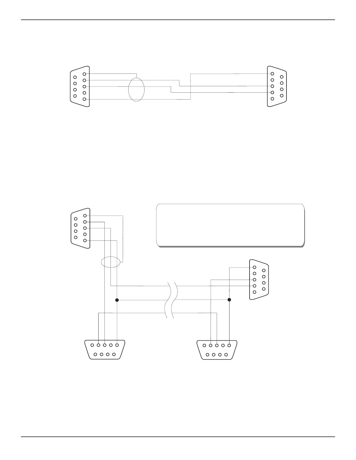
CONNECTOR
DB9S
CONNECTOR
DB9S
PCS 400
COMPUTER
5
1
SHLD
TX
RX
SIG. GND
2
3
Figure 4.1 - Single Drop Cable
2
1
352
3
HOST
52
3
5
2
3
PCS 400
End
DB9
CONNECTOR DB9S
P
4
CONNECTOR DB9S
P
4
5
RXD
SHLD
SIG. GND
TXD
2. If a PCS 400 is removed from the loop then pins 2
and 3 of the vacated connector must be jumpered
for the remaining PCS 400(s) to communicate.
1. Connectors are female, shown from the wired end.
NOTES:
Figure 4.2 - Multi-Drop Cable
REMOTE OPERATION PCS 400
4-18 www.mensor.com