remain active until either another transducer is
selected to be active (by local or remote command),
or the AUTORANGE is enabled. Relief valves have
been incorporated to prevent damage due to fast
pressure transients.
To enable AUTORANGE:
Press [2nd]
[3] LIMITS
[=]
[+] or [–] until the display shows:
SELECT ACTIVE RANGE (USE +,-,=,CE)
ANY INTERNAL TRANSDUCER (AUTORANGE)
then press [=] to enable AUTORANGE.
To disable AUTORANGE:
Press [2nd]
[3] LIMITS
[=]
[+] or [–] until desired transducer is
displayed
then press [=] to range-hold using the
displayed transducer.
CONTROL MODES
The CONTROL mode provides the user the means
to output a specific, highly regulated pressure. Two
different control modes are a standard feature of
the PCS 400. The two standard modes are identified
as NORM (for NORMAL), and RATE under the
LIMITS menu heading.
NORMAL Mode
NORMAL control mode is the default mode and is
indicated on the top line of the display by NORM.
This mode achieves stable pressure at the new
control point in the shortest time.
RATE Mode
RATE control mode is indicated by RATE on the
top line of the display, and should be selected when
overshoot must be kept to a minimum. RATE mode
provides a means to control the rate of change in
pressure units. This mode is useful where rapid
pressure changes would be harmful to sensitive
devices under test (DUTs). Overshoot in RATE
mode is typically less than in NORMAL mode, but
the time to achieve stable pressure will be longer
than in NORMAL mode. The minimum and maxi-
mum controllable rates of pressure change are
dependent on the FS range of the PCS 400 as shown
in the following table.
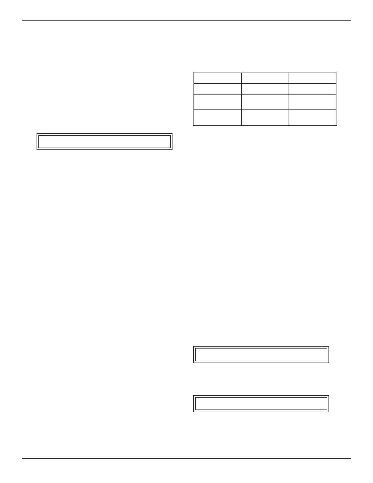
Table 3.2 – Min/Max Rate
Full Scale Minimum Maximum
£5 psi 0.00025 psi/sec 0.1 psi/sec
>5andupto
100 psi
0.0025 psi/sec 1 psi/sec
>100 and up to
1000 psi
0.025 psi/sec 10 psi/sec
The maximum pressure rates shown above are
based on external volumes of 0.5 liter, or less.
Larger volumes will reduce the maximum rate that
can actually be achieved. When a new control point
is entered the PCS 400 will attempt to control the
pressure change at the last rate value specified. As
the pressure approaches the control point the con-
trol rate of change will decrease to prevent over-
shoot at the commanded point. Because of this
automatic slow-down it may not be possible to
achieve the set rate between small pressure steps.
Note that when the [S] for pressure stable appears
in the display it indicates stability at the control
point rather than indicating a stable pressure rate.
Multiple Internal Transducers
For instruments with multiple internal
transducers, in CONTROL mode with
AUTORANGE on the PCS 400 automatically acti-
vates the lowest range transducer that can effec-
tively measure the commanded pressure. For
example, an instrument that has internal
transducers of 150 psi and 30 psi would automat-
ically switch to the 30 psi transducer when com-
manded to control at 10 psi. The address of the
active transducer (@ 01) is included on the second
line of the display as shown in the screen, below.
The [S] signifies that the controlled pressure is
stable at the measured value displayed.
CONTROL PRESS:(NORM)10.0000 PSI A
MEASURED @ 01: 10.0000 PSI A [S]
Likewise, if the control point is set to 31 psi while
in AUTORANGE the system will default to the 150
psi primary transducer and display as follows.
CONTROL PRESS:(NORM)31.000 PSI A
MEASURED: 31.000 PSI A [S]
Notice in particular the two differences; 1, the
transducer ID following MEASURED has disap-
peared; and 2, there is one less digit of resolution.
PCS 400 LOCAL OPERATION
www.mensor.com 3-9