Maintenance of the Vacuum Gauge/Tube
If the gauge does not work, try the following:
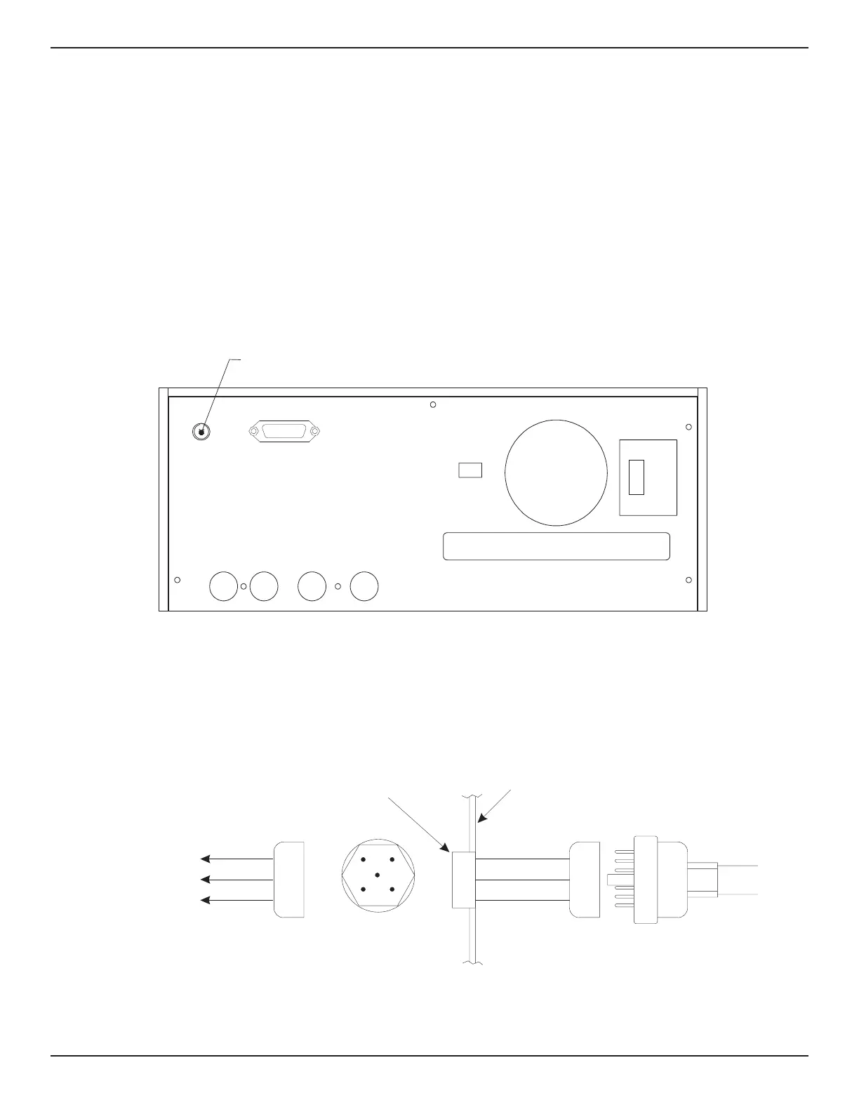
1) Be sure that the power to the vacuum gauge
has not failed. Check the connections into the
vacuum gauge and trace power to the gauge
tube socket. Approximately l15 VAC can be
measured with a test set between pins 3 & 5
and 5 & 7 on the octal socket located inside
the PCS 400 (requires removing only the top
panel of the instrument);
2) Try a new gauge tube. Generally, this is the
most common cause of failure. The circuit can
be rapidly checked by plugging in a new tube
and observing an ‘ATM’ reading on the indica-
tor, without required installation in the sys-
tem. Note that the open end of the gauge tube
should point down for this check.
MEASURE/
CONTROL
REFERENCE
EXHAUST SUPPLY
IEEE STD 488 PORT
SH1, AH1, T6, L4,
SR1, RL1, PP0,
DC1, DT1, E2, C0
SERIAL PORT
FUSE: 250V/1.5A
“This equipment complies with the requirements
in Part 15 of FCC Rules for a Class A computing
device. Operation of this equipment in a
residential area may cause unacceptable
interference to radio and TV reception requiring
the operator to take whatever steps are necessary
to correct the interference.”
Vacuum
auge
onnector
Figure 8.6 - Rear Panel Showing Vacuum Gauge Connector
DV6M
Gauge Tube
PCS 400
Rear Panel
To
Model VT-6
Vacuum Gauge
Octal
Socket
Connector
Amphenol #126-223
Connector
Amphenol #126-216
3AA
B
A
H
D
E
7DD
5HH
Figure 8.7 - VT-6 Gauge Tube Wiring
OPTIONS PCS 400
8-8 www.mensor.com