iii. Ensure that the SAE cable is inserted fully into both the node
and solar panel arm.
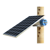
iv. Verify that the solar panel arm’s SAE port is soldered
properly to the black junction box on the back of the panel.
v. Open the node’s core to verify that the solar harness is
plugged into the node’s PCB. Verify that each SAE connector
is connected to the harness as well.
Issue 6: Charging the node via PoE is not working.
i. The node must have a PoE power module installed; verify
this by making sure that it is the correct configuration. This
can be done by checking the serial number located on the
node’s outer case, which should have an “D” as appropriate.
ii. Ensure the node can be turned on with at least 20% battery
and can enter states normally (its LED indicators light up).
iii. Verify that Gateway Mode is working on the node. See Issue
#7 for additional ethernet troubleshooting instructions.
iv. When charging via PoE, ensure that:
1. The PoE switch or injector being used to charge the node
has been tested to properly function and is rated at a
minimum of 15.4W using the 802.3af/at standard.
2. If applicable, the PoE switch has PoE output enabled on
the connected ethernet port.
3. If there are any LED indicator lights on the PoE switch or
injector, they are showing the correct state (both an active
ethernet connection and enabled power to the node).
4. If the lack of power is deduced by battery level, ensure
that enough time has been given to charge the node due
to the power module’s 13W limit. Turn the node off for a
full day while leaving it to charge and verify that the
battery level changed. Note that this may take up to 5
times longer than standard USB-C charging.
v. The production firmware may need to be updated - please
refer to section 9.b - Upgrading Node Firmware .
vi. Open the node’s core to verify that the internal USB-C cable
is securely plugged into the node’s PCB.