2.7.3 Connections with Separate Normal and Bypass AC sources (2 Mains)
CAUTION: This connection requires isolation Transformer Module. Call MGE
Technical Support for details.
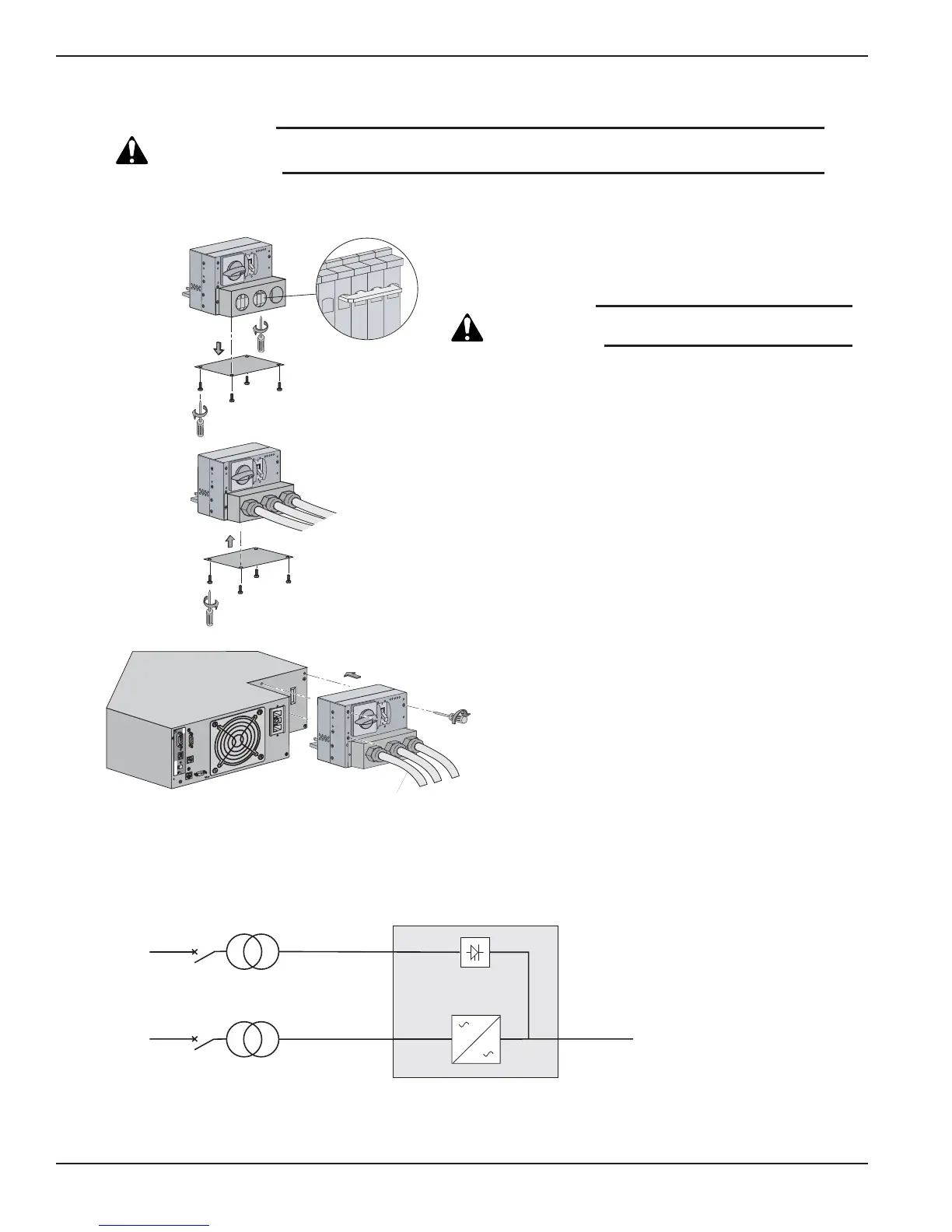
Figure 2-14: Normal AC and Bypass AC inputs, Output Cables Installation, and Simplified Connection Diagram.
EX 5/7/11RT Systems
Installation2 — 16 86-86000-00 B00
4
Card Settings
RS232 Download
66074
UPS
data
Reset
100 10
1 2
ON
ETHERNET
IP=
MAC=00E0D8FF855E
1
3
Output
Bypass
Normal
OF
F
O
O
F
F
O
O
F
F
O
To Load or
Transformer Module
(if applicable)
2
L3
L1
MAINS 2
BYPASS AC
NORMAL AC
MAINS 1
LOAD
With separate Normal and Bypass AC inputs, supplied by separate sources.
Isolation
Transformer
(PN 86211)
Proceed as follows:
1. Remove the cover plate under the I/O Box. Loosen the
terminal blocks L1 and L3, and remove the jumper.
CAUTION: Always connect the earth ground wire
first.
2. Install Normal AC, Bypass AC and output cables as shown.
3. Reinstall the cover plate under the I/O Box with four screws.
4. Secure the I/O Box to the Power Module with three screws.
See section 2.7.2 for connecting EX RT Transformer
module, if applicable.