69D0023 17
V
V
V
V
V
V
V
V
D
L
E
B
C
F
B
B
B B
B
M
I
A
A
J
H
G
A
Operable
Fixed
Closed
Fixed
Closed
Opera-
ble
K
A
A
A
G
CDV Series Gas Fireplace
VENT INSTALLATION
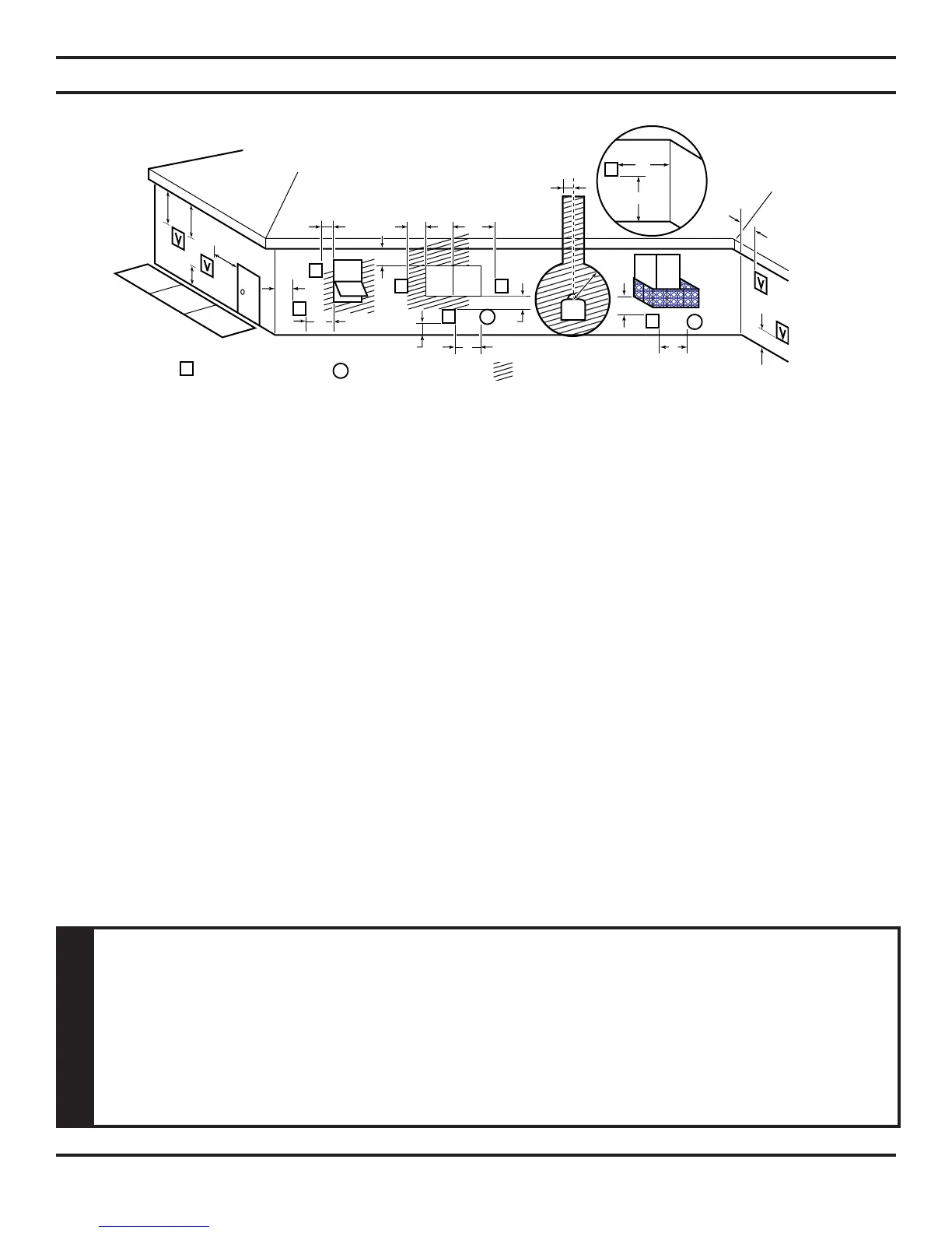
Figure 11 - Horizontal Vent Termination Location
Vent Terminal Air Supply Inlet Area Where Terminals Not Permitted
Inside Corner Detail
FOR HORIZONTAL TERMINATION
MINIMUM DISTANCES
A = Clearance above the grade, a veranda, porch, deck, or balcony [*12" (305 mm) minimum].
B = Clearance to window or door that may be opened [*12" (305 mm) minimum].
C = Clearance to permanently closed window [*minimum 12" (305 mm) recommended to prevent condensation
on window]
D
= Vertical clearance to ventilated soft located above the terminal within a horizontal distance of two (2) feet
(610mm) from the centerline of the terminal [18" (457 mm) minimum].
E
= Clearance to unventilated softs [12" (305 mm) minimum].
F = Clearance to an outside corner. Figure 12.
G = Clearance to an inside corner. Figure 12.
H = *Not to be installed above a gas meter/regulator assembly within three (3) feet (914mm) horizontally from the
centerl ine of the regulator.
I = Clearance to service regulator vent outlet [*3' (914mm) minimum].
J = Clearance to non-mechanical air supply inlet to building or the combustion air inlet to any other appliance
[*12" (305mm) minimum].
K = Clearance to a mechanical air supply inlet [*6' (1829 mm) minimum].
L
= Clearance above a paved sidewalk or paved driveway located on public property [
**
7' (2133mm) minimum].
M
= Clearance under veranda, porch, deck, or balcony. Refer to Figure 9 [*In Canada 12" (305 mm) minimum].
* As specied in CSA B149 Installation Codes. Note: Local codes or regulations may require different
clearances.
** A vent must not terminate directly above a sidewalk or paved driveway, which is located between two single-
family dwellings and serves both dwellings.
*** Only permitted if veranda, porch, deck, or balcony is fully open on a minimum of two sides beneath the
oor.
WARNING
1
2