69D0023 33
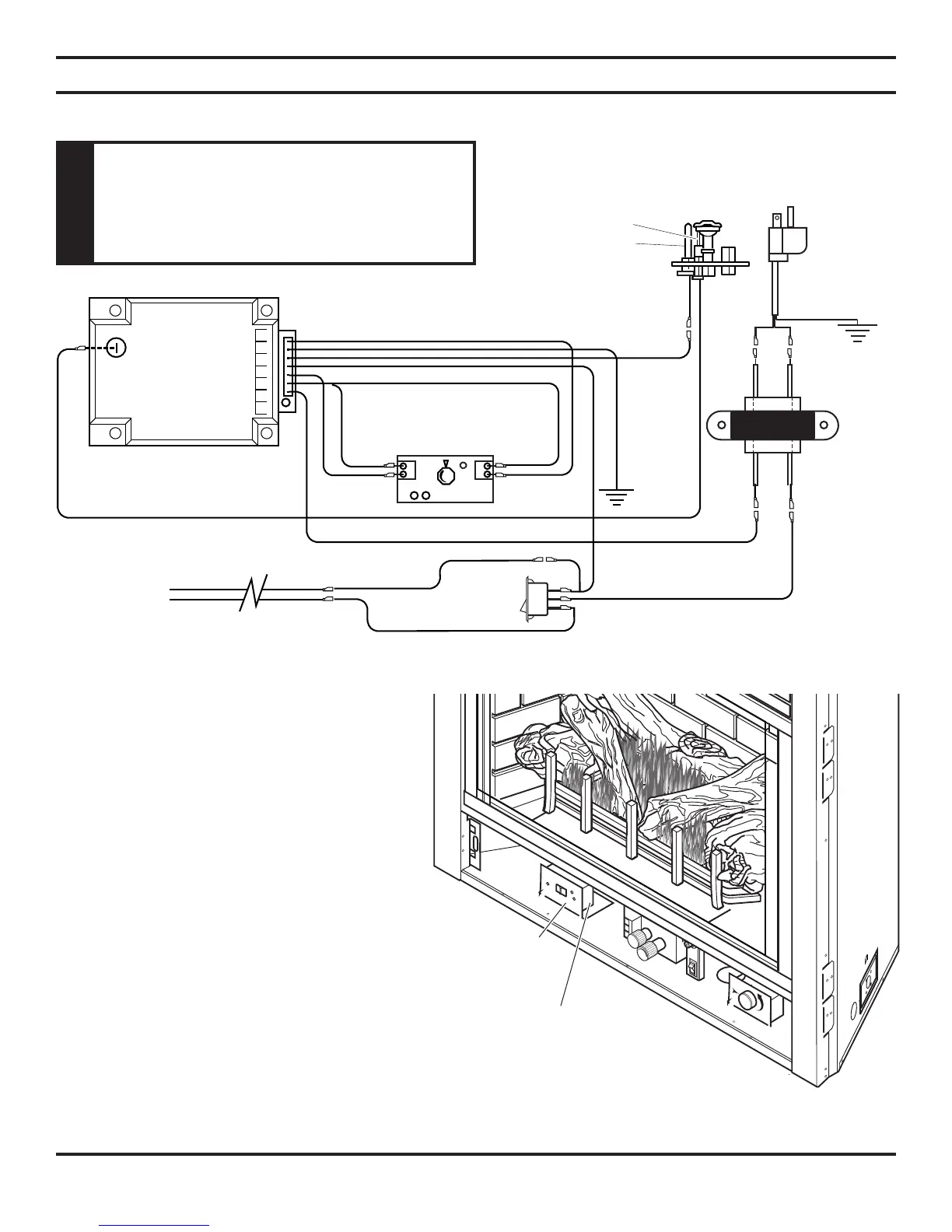
#1 #2 #3 #4 #5 #6 7#
Electronic Valve
GRAY #7
RED #2
RED #2
BLACK #4
GREEN #6
BLUE #1
BLUE
YELLOW
YELLOW
WHITE #3
MAGENTA #5
15’ Wall Switch Wire
BLACK
WHITE
Switch
RS
OFF
ON
Transformer
Secondary
24V
WHITE
WHITE
GREEN
BLACK
BLACK
Primary - 120V
To Junction Box
Pilot Assembly
Spark
Sense
Ignition Module (Synetek)
HI
LO
EV1 EV2
CDV Series Gas Fireplace
ELECTRICAL INSTALLATION
ELECTRONIC PILOT IGNITION WIRING
REMOTE WALL SWITCH
Position the wall switch. Do not extend beyond
the 15 feet of wire.
OPTIONAL DC REMOTE SYSTEMS
See section entitled Hearth Mount in the Millivolt
hand held remote instructions supplied with the
remote.
1. Using a at head screw driver, bend the
“remote” tabs up from the bottom of the
replace. Figure 45
2. Follow the instructions on remote control to
snap the remote cover plate to the remote
receiver
3. Connect the wire terminal from the remote
receiver. This replaces the 15' wall switch
connection to the switch. Figure 44
4. Use the screws that came with the remote
control to mount the remote receiver cover
to the bent up “remote” tabs. Figure 45
Figure 44 - Remote Wall Switch Wiring Diagram
Remote Control
Figure 45 - Remote Control Location
“Remote” Tabs
WARNING
Do not connect 110-120 VAC to the