69D0023 21
40
38
36
34
32
30
28
26
24
22
20
18
16
14
12
10
8
6
4
2
2 4 6 8 10 1214 16 1820
eg: A
CDV Series Gas Fireplace
VENT INSTALLATION
HORIZONTAL TERMINATION CONFIGURATIONS
-
strictly adhered to.
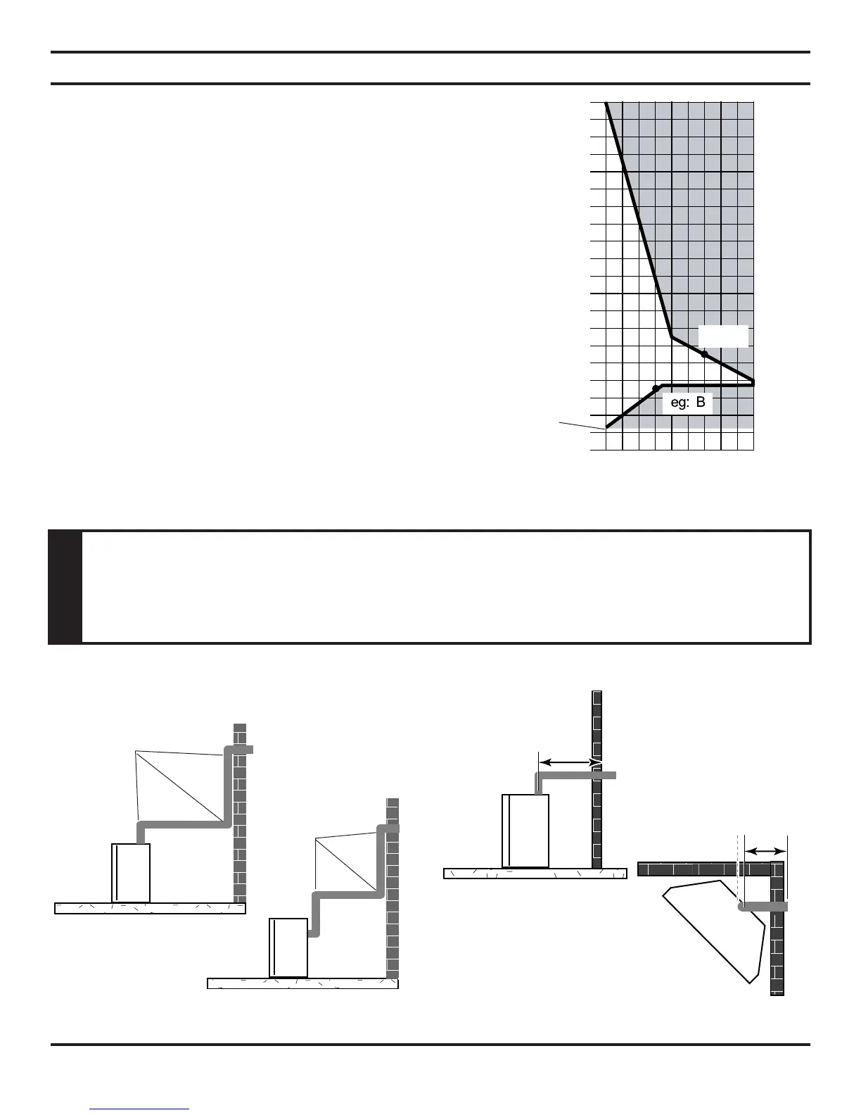
The Vent Graph, showing the relationship between vertical and hori-
zontal side wall venting, will help to determine the various dimensions
allowable. Figure 20
NOTE: Horizontal sections of this vent system require a minimum of 3"
clearances to combustibles at the top of the ue unless the vertical run is
7
1
/2 feet or higher (top vent units only), the clearances for the horizontal
run is 1" at the top, and 1" clearance at the sides and bottom until the
ue penetrates the outside wall. A minimum 1" clearance all around the
ue is acceptable at this point of penetration.
Vertical sections of this vent system require a minimum of 1" clearance
to combustibles on all sides of the pipe.
When vent exits through foundations less than 20" below outcrop, the
termination must be ush up with outcropped wall above.
It is best to locate the replace in such a way that minimizes the number
of offsets and horizontal vent length.
The horizontal vent run refers to the total length of vent pipe from the
ue collar of the replace (or the top of the Transition Elbow) to the
face of the outer wall.
Figure 21 - Maximum Three (3) 90° Elbows
Per Installation
• The maximum number of 90° elbows per side wall installation is three (3). Figure 21
• If a 90° elbow is tted directly on top of the replace ange the maximum horizontal vent run before the ter-
mination or a vertical rise is 36” (914 mm). Figure 22
Figure 22 - Maximum Horizontal Run with No Rise
3 x 90°
Elbows
3 x 90°
Elbows
36"
Max.
36"
Max.
Figure 20 - Rear Wall Venting Graph
Horizontal Dimension From the Outside of
Termination to the Back of the Fireplace
Vertical Dimension From the Floor of Unit to the Center of the
Horizontal Vent Pipe
20"
WARNING
attached directly to the rear of the unit is NOT INCLUDED in the following criteria and
venting layouts.