Do you have a question about the Micronta 22-195A and is the answer not in the manual?
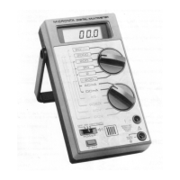
Describes the multimeter's design, technology, and general capabilities.
Lists core functionalities like auto-ranging, data hold, continuity, diode check, hFE, and memory.
Explains the digital display, bar graph, and various indicator lights on the meter.
Details the purpose of input jacks and control switches for operation.
Describes measuring value indicators, bar graph, and specific indicators (AC, BATT, etc.).
Explains the purpose of the 10A, +, and - input jacks for connections.
Details the hFE terminal and PNP-NPN switch for transistor testing.
Covers range control, buzzer, data hold, memory, and power switches.
Describes the detented handle and battery/fuse compartment for usability.
Lists test clip harness and banana test leads supplied with the unit.
Explains markings for current and voltage limits on the meter.
Covers warnings for high voltage and common terminal use for user safety.
Step-by-step guide for battery installation and understanding the low battery indicator.
Notes on test lead rating and meter voltage limits for safe operation.
Describes how to adjust the handle for optimal viewing angles.
Describes powering on the meter and its self-test sequence.
Guides the user on practicing range selection for familiarization.
Lists available functions, ranges, and corresponding display formats.
Explains range control behavior and phantom readings.
Step-by-step guide for performing voltage measurements on the meter.
Explains how decimal points indicate the measurement range on the display.
Details for measuring 3-phase AC voltages and associated warnings.
Describes how to measure AC voltage on a DC source bias.
Provides safety tips for probing high voltage circuits.
Details how to connect for 300mA and 10A current measurements.
Explains series connection and critical warnings for current measurements.
Details the steps to connect probes for resistance measurements.
Explains stabilizing high readings and using unit display for range.
Provides table of voltage and current available for each resistance range.
Explains the protection circuit for resistance ranges against over-voltage.
Notes on accounting for internal resistance of leads when measuring small resistances.
Explains how to use the continuity function and its audible feedback.
Details the steps and interpretation for checking diodes with the meter.
Explains how to connect and measure transistor hFE (current gain).
Explains reading the hFE value and a critical safety warning.
Describes how the bar graph displays measured data and polarity.
Explains how to start, store, and recall maximum/minimum values.
How to stop and clear the memory function, and bar graph display.
Explains how to recall the maximum and minimum values stored in memory.
Explains how values are determined, including overrange and auto-range.
Provides technical details about the memory function's timing and converters.
Explains how memory stores values and handles polarity changes.
Provides examples of maximum and minimum values retained in memory.
Shows examples of memory function with non-linear inputs.
Suggests using Data Hold for retaining data after probe disconnection.
Explains how to freeze the display and retain data, even after removing probes.
Notes on conditions that may cancel Data Hold or make switches inoperative.
Explains buzzer sounds for renewed values and exceeding limits.
Clarifies buzzer behavior in continuity mode and auto-ranging.
Explains switching to manual range and adjusting with UP/DOWN.
Details how to switch back to autorange mode from manual.
Provides safety precautions and steps for removing the fuse.
Explains how to insert a new fuse correctly into the compartment.
Details closing the battery/fuse compartment and relevant warning.
Covers general maintenance, environmental limits, and damage prevention.
Lists essential safety recommendations for operating the multimeter.
The detailed electronic schematic of the multimeter's internal circuitry.
Explanations of notes related to components and switch functions.
Details the 90-day warranty period and what it covers.
Lists limitations, exclusions, and consumer legal rights.
| Diode Test | Yes |
|---|---|
| Continuity Buzzer | Yes |
| Fuse Protection | Yes |
| DC Voltage Ranges | 0.1V, 10V, 50V, 250V, 1000V |
| AC Voltage Ranges | 10V, 50V, 250V, 1000V |
| DC Current Ranges | 2.5mA, 25mA, 250mA |
| Battery | 9V |
| dB Range | -20 to +62 dB |
| Battery Type | AA and 9V |