In-Application Programming Using PCIe Interface
DG0584 Demo Guide Revision 5.0 10
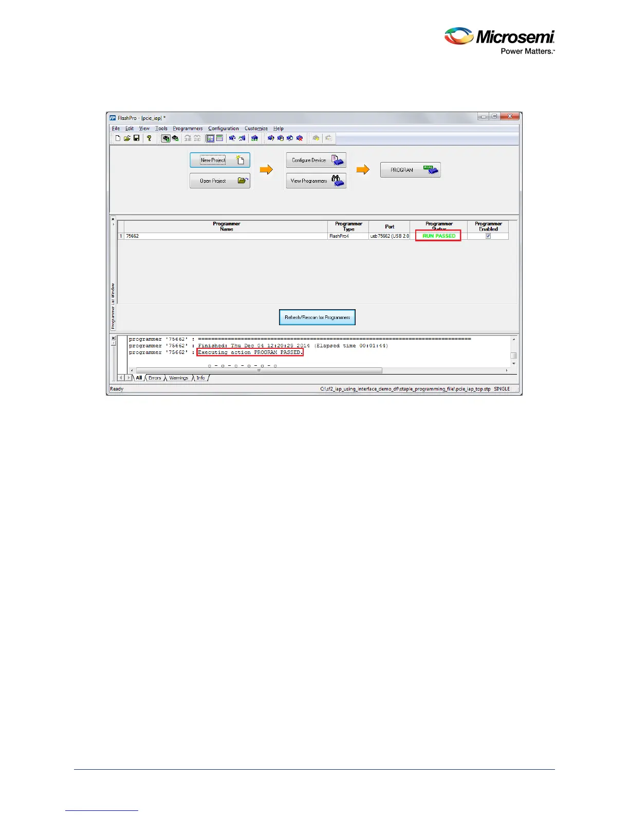
4. Click PROGRAM to start programming the device. Wait until the Programmer Status is changed to
RUN PASSED, as shown in the following figure.
Figure 8 • FlashPro Programming Passed
2.5 Connecting the SmartFusion2 Security Evaluation Kit
Board to Host PC
The following steps describe how to connect the Security Evaluation Kit board to the host PC:
1. After successful programming, switch OFF the SmartFusion2 Security Evaluation Kit board and shut
down the host PC.
2. The following steps describe how to connect the CON1–PCIe Edge Connector either to the host PC
or laptop:
• Connect the CON1–PCIe Edge Connector to the host PC PCIe Gen2 slot or Gen1 slot. This
demo is designed to run in any PCIe Gen2 compliant slot. If the host PC does not support the
Gen2 compliant slot, the design switches to the Gen1 mode.
• Connect the CON1–PCIe Edge Connector to the laptop PCIe slot using the express card
adapter. If you are using a laptop, the express card adapters support only Gen1 and the design
works on Gen1 mode.
Note: The host PC or laptop must be switched OFF while inserting the PCIe Edge Connector. If the system is
not switched OFF, the PCIe device detection and selection of Gen1 or Gen2 do not occur properly.
3. Switch ON the power supply switch, SW7.