Technical Information
18
CVA 610/CVA 615 Coffee Systems
4.0 Description of Function
4.1 Door Switch (S24)
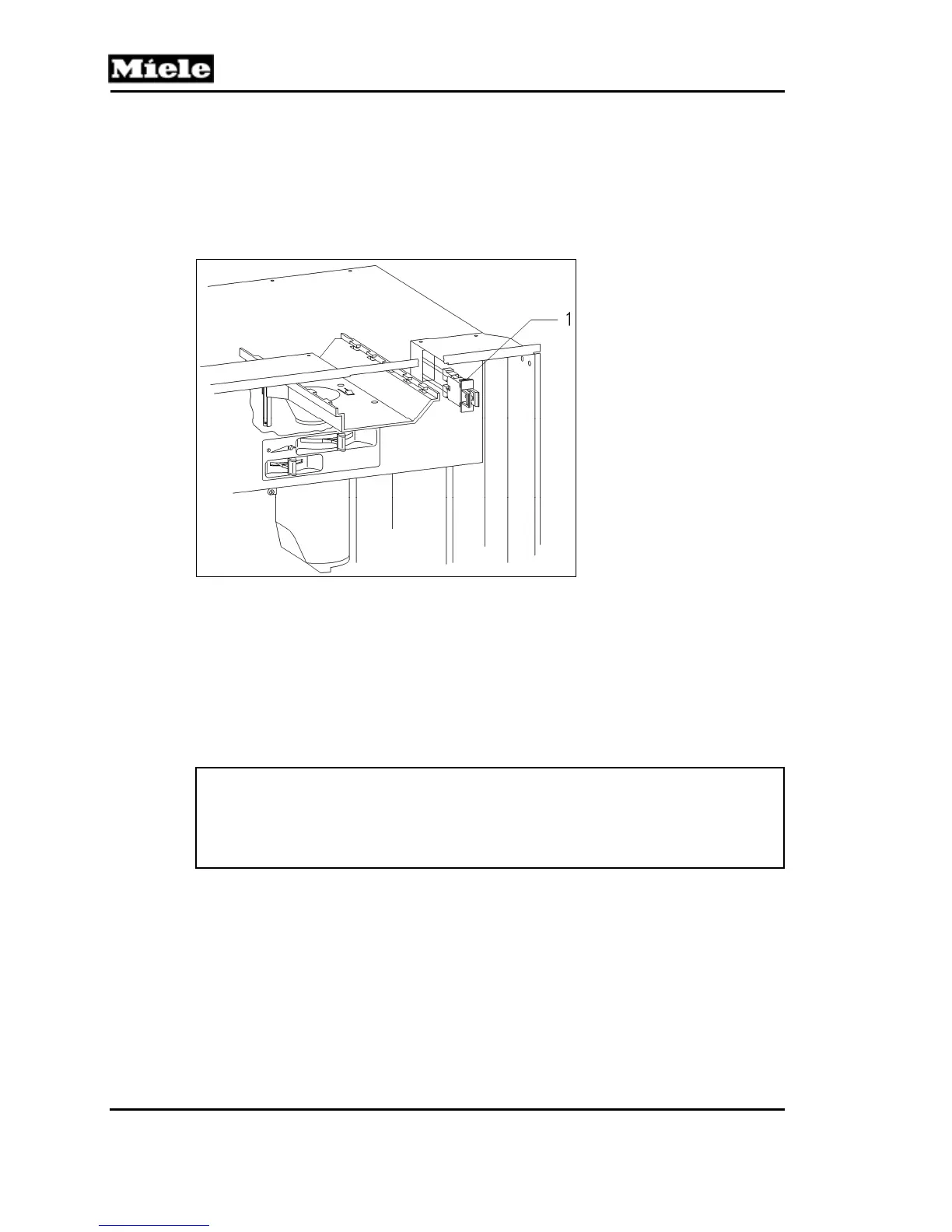
The door switch (Figure 4-1, Item 1) interrupts the main power circuit when the door
is opened.
Figure 4-1: Door Contact Switch (S24)
4.2 Overflow Switch (B8/3)
The overflow switch is mounted to the bottom of the casing. The associated float
(with internal magnet) is located within the drip tray. Should a leak develop, water will
flow into the drip tray. The float rises and the overflow switch becomes actuated. The
electronic then displays the “Water System Fault” message and switches the
appliance off.
Note:
When the service mode is accessed, the top line of the display shows the
switches that are activated. An “A” will be displayed if the overflow switch is
actuated (i.e. water present in the bottom of the appliance). Refer to
Section 6.2 for more information on the service mode.
4.3 Brew Unit
4.3.1 Cleaning and Care
The brew unit is a mechanically operated component that is subjected to high forces,
and therefore may become clogged after a long period of use. To ensure correct
operation of the brew unit, it is essential to clean it regularly and apply silicone
grease to the moving parts. Refer to Sections 5.30, 5.31 and 5.32 for further
information and procedures.

 Loading...