Technical Information
21
CVA 610/CVA 615 Coffee Systems
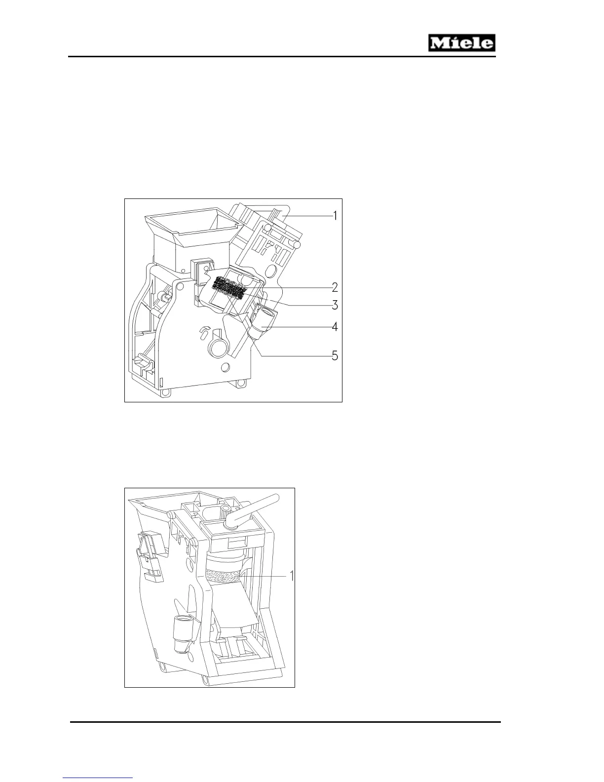
the top filter (Figure 4-5, Item 2) and bottom filter (Figure 4-5, Item 5).
6. The water pump is energized to pump the water through the hot water/coffee
nozzle and into the brew unit via the water connection socket (Figure 4-5, Item
4). The hot water forces through the brew unit and the compressed grounds
(Figure 4-5, Item 3) and exits the top of the brew unit via the drain spout (Figure
4-5, Item 1).
With the door of the appliance closed, the drain spout makes contact with the
dispensing system on the front of the appliance. The user’s cup is filled with coffee
as the coffee flow exits.
Figure 4-5: Brew Unit Components
7. The drives are energized (in reverse) and move the brew unit toward the "home"
position. As this action occurs the coffee chamber moves upward and releases
the used compressed coffee grounds into a “puck” (Figure 4-6, Item 1).
8. The drives continue, returning the brew unit to the "home" position (as
determined by the home position switch).
Figure 4-6: Brew Unit, Showing Compressed Coffee “Puck”
1 Outlet
2 Top filter
3 Compressed coffee (puck)
4 Water connection socket
5 Bottom filter

 Loading...