Technical Information
19
CVA 610/CVA 615 Coffee Systems
4.3.2 Removal from the Appliance
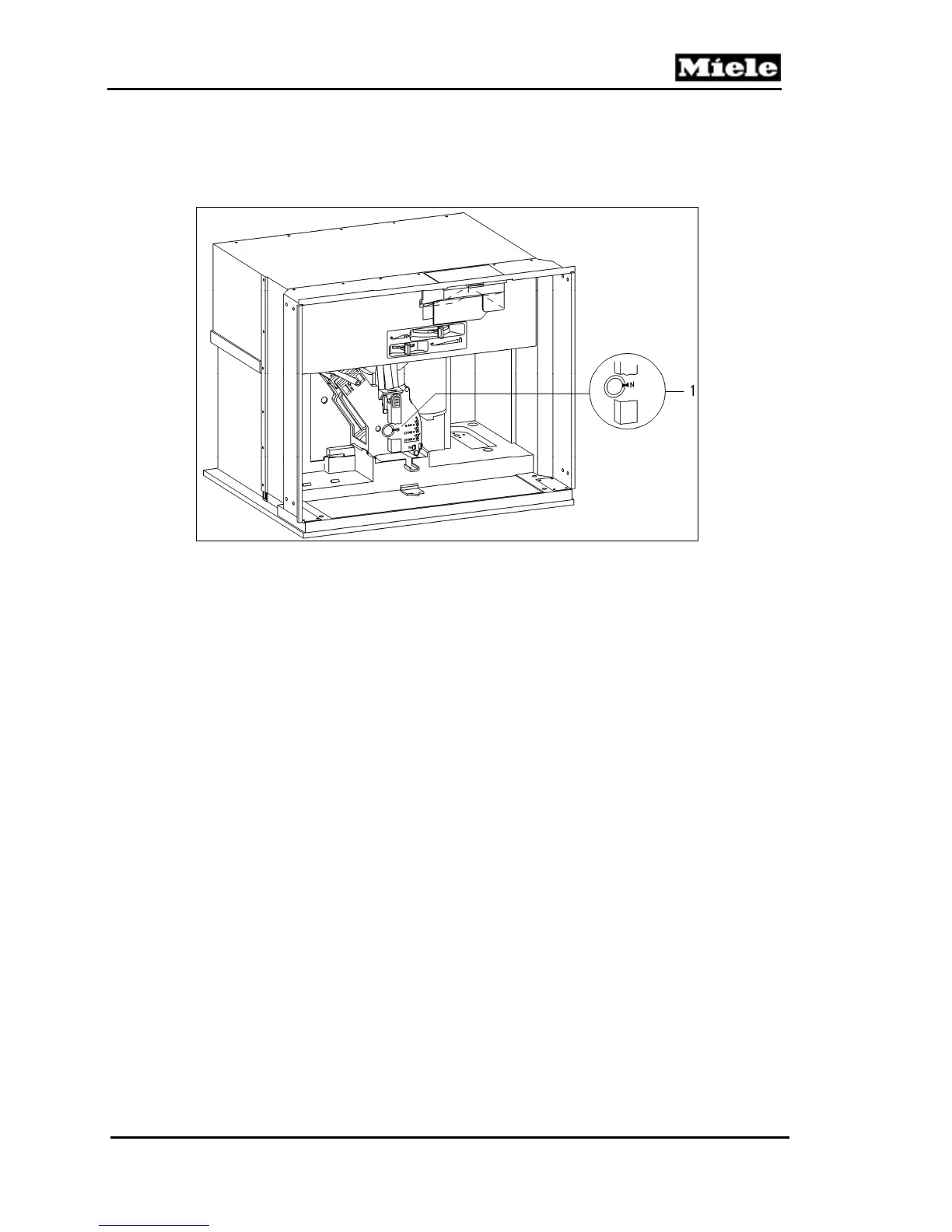
The brew unit must be in the “home” position (see Figure 4-2, Item 1) before it can
be removed from the appliance.
Figure 4-2: Brew Unit in the “Home” Position
4.3.3 Drive and Water Connections
When the brew unit is installed, it locks into position. The locking mechanism switch
lug (Figure 4-3, Item 3) activates the brew unit present switch (Figure 4-3, Item 4).
The drive shaft (Figure 4-3, Item 6) engages with the drive shaft socket (Figure 4-3,
Item 1) to drive the brew unit.
When the brew unit moves into the “brewing” position, the hot water/water
connection socket (Figure 4-3, Item 2) connects to the nozzle on the hot water/coffee
heater (Figure 4-3, Item 5) to let water pass through the coffee.

 Loading...