EasyManua.ls Logo

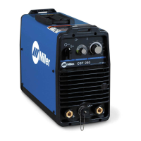
Miller CST 280 - User Manual

Miller CST 280
56 pages
Print Icon
To Next Page IconTo Next Page
Loading...
Processes
Description
Stick (SMAW) Welding
OM-258 035F 2015−08
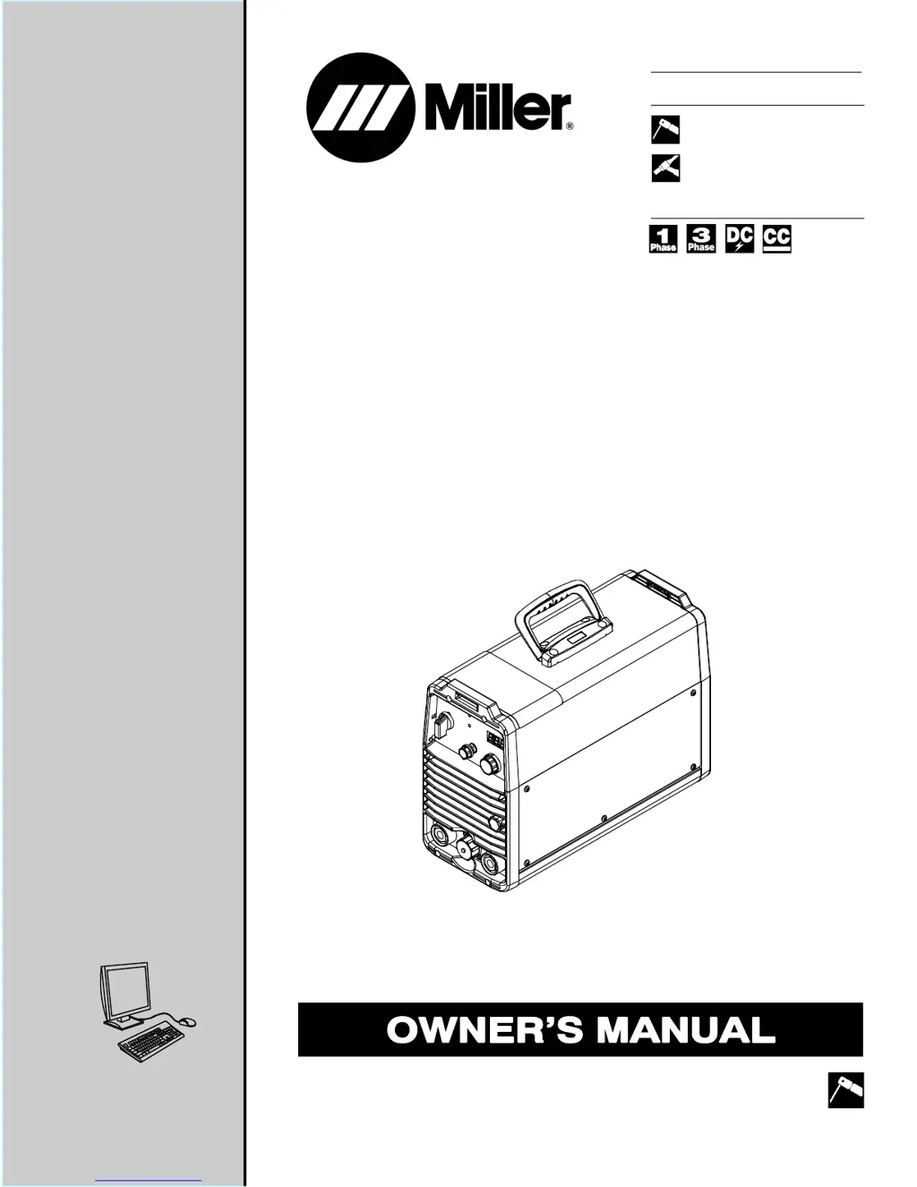
Arc Welding Power Source
CST 280 And CST 280 VRD
With Meter
TIG (GTAW) Welding
File: Stick (SMAW)
Visit our website at
www.MillerWelds.com

Table of Contents

Questions and Answers

  • R
    Rebecca HicksAug 27, 2025
    What to do if my Miller CST 280 has voltage loss?
    • J
      James WernerAug 27, 2025
      If your Miller Welding System is experiencing a voltage loss, there are several potential causes. First, check the Vfb leads for proper wiring and connection to the output studs and PC13. Second, check for any short circuits across the output studs. Next, inspect the IGBT PM1 or PM2 on PC2 and replace PC2 if necessary. Also, a faulty PC13 could be the reason, so try replacing it. If you observe low OCV initially with LEDs flashing when a load is applied, the PM1 or PM2 on PC2 might be faulty, suggesting PC2 replacement. Finally, a faulty C3 could also cause voltage loss, so consider replacing C3.
  • D
    dennisfrenchAug 25, 2025
    How to fix a Miller Welding System when the fan is not operating?
    • J
      John EricksonAug 25, 2025
      If your Miller Welding System's fan is not operating, start by checking for any obstructions that may be blocking the fan's movement and remove them. If there are no obstructions, the fan itself may have failed, and you should have a factory-authorized service agent check the fan motor. A faulty PC13 can also cause the fan to fail; consider replacing PC13.
  • T
    Theresa BurchAug 23, 2025
    Why is the weld output reduced on my Miller Welding System?
    • L
      leevictoriaAug 25, 2025
      If your Miller Welding System is experiencing reduced weld output, it might be due to exceeding the single-phase rating, resulting in output foldback from excessive input current. Try reducing the output to 200 amperes or less. It could also be a combination of high output VA and a low 230V line. In this case, check both the line voltage and your weld settings.

Summary

SECTION 1 - SAFETY PRECAUTIONS - READ BEFORE USING

Symbol Usage

Explains symbols for hazards, warnings, and notices.

Specific Welding Hazards

Details specific risks like fumes, arc rays, fire, explosion, EMF, noise, and cylinders.

Arc Welding Hazards

Introduces general hazards associated with arc welding processes.

SECTION 3 - DEFINITIONS

Additional Safety Symbols and Definitions

Explains safety symbols and their meaning.

SECTION 4 - SPECIFICATIONS

Duty Cycle And Overheating

Explains duty cycle percentages and consequences of overheating.

SECTION 5 - INSTALLATION

Weld Output Terminals And Selecting Cable Sizes

Details how to select appropriate weld cable sizes based on amperage and cable length.

Selecting 208 - 230 Volts AC Single;Three Phase Input Voltage

Guides on how to select the correct input voltage for the unit.

Electrical Service Guide

Provides recommendations for electrical service, circuit protection, and conductor sizing.

Connecting 1-Phase Input Power

Details the steps and components for connecting 1-phase input power.

Connecting 1-Phase Input Power (Continued)

Provides further instructions for connecting 1-phase input power and safety notes.

Connecting 3-Phase Input Power

Details the steps and components for connecting 3-phase input power.

Connecting 3-Phase Input Power (Continued)

Provides further instructions for connecting 3-phase input power and safety notes.

SECTION 6 - OPERATION

Controls

Identifies and explains the function of various controls on the unit.

Process Select Control

Explains how to select different welding processes and electrode types.

SECTION 7 - MAINTENANCE AND TROUBLESHOOTING

Troubleshooting

Details common problems, possible causes, and remedies based on LED flash codes.

Troubleshooting (Continued)

Provides further troubleshooting information for various error codes and conditions.

SECTION 9 - SELECTING AND PREPARING A TUNGSTEN FOR DC OR AC WELDING WITH INVERTER MACHINES

SECTION 10 - GUIDELINES FOR TIG WELDING (GTAW)

Warranty

Miller CST 280 Specifications

General IconGeneral
Amperage Range5-280 A
Input Frequency50/60 Hz
ProcessStick (SMAW)
Rated Output280 A
Input Voltage208 V / 230 V / 460 V / 575 V

Related product manuals