EasyManua.ls Logo

Miller Multimatic 215 - User Manual

Miller Multimatic 215
72 pages
Print Icon
To Next Page IconTo Next Page
Loading...
OM-272989A 201603
Multimatic 215
Visit our website at
www.MillerWelds.com
ProcessesProcesses
Description
Multiprocess Welding
Arc Welding Power Source
Wire Feeder
File: Multiprocess
t

Table of Contents

Questions and Answers

  • A
    Andrea TravisSep 8, 2025
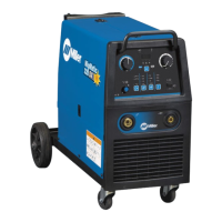
    Why is the fan not operating on my Miller Multimatic 215?
    • J
      Jamie TaylorSep 8, 2025
      The fan on your Miller Welding System might not be operating for several reasons: * The unit may not be warmed up enough to require fan cooling. * There might be something blocking the fan movement; check for and remove any obstructions. * If neither of these resolves the issue, have a Factory Authorized Service Agent check the fan motor and control circuitry.
  • P
    psimpsonSep 7, 2025
    What to do if my Miller Multimatic 215 displays 'Stuck electrode-Free tungsten to clear error'?
    • Y
      yadamsSep 7, 2025
      If your Miller Welding System displays 'Stuck electrode-Free tungsten to clear error', it means the tungsten electrode has become stuck in the weld puddle and turned the output off. Remove the tungsten from the workpiece, and the output will turn back on after about one second.
  • C
    Caitlin KellyAug 22, 2025
    What to do if my Miller Welding System says 'Overtemp'?
    • T
      Tammy KimAug 22, 2025
      If your Miller Welding System displays an 'Overtemp' message, it means the internal temperature has exceeded the maximum limit. Allow the unit to cool down. If the fan isn't running, it is recommended to contact Miller Electric Mfg. Co. service department.
  • T
    Tammy HansonSep 4, 2025
    Why is there no weld output from my Miller Multimatic 215 Welding System and the unit is completely inoperative?
    • S
      Spencer KhanSep 4, 2025
      If there is no weld output and the Miller Welding System is completely inoperative: * Ensure the line disconnect switch is in the On position. * Check and replace line fuses if necessary, or reset the supplementary protector. * Ensure the power cord is plugged in and the receptacle is receiving input power.
  • E
    Eric GoodmanSep 3, 2025
    What to do if my Miller Multimatic 215 displays 'Shorted trigger? Release 4-pin trigger to clear error'?
    • S
      Sarah NelsonSep 3, 2025
      If your Miller Welding System displays 'Shorted trigger? Release 4-pin trigger to clear error', it means the MIG gun or spool gun trigger is engaged on power up. Release the 4-pin trigger to clear the error.
  • S
    Scott PowellSep 1, 2025
    What to do if my Miller Multimatic 215 displays 'Shorted trigger-Release 8-pin trigger to clear error'?
    • R
      Ryan MarquezSep 1, 2025
      If your Miller Welding System displays 'Shorted trigger-Release 8-pin trigger to clear error', it means the 8-pin trigger is engaged on power up. Release the 8-pin trigger.
  • D
    Daniel JonesAug 31, 2025
    What to do if my Miller Multimatic 215 displays 'Shorted trigger-Release trigger to clear error'?
    • C
      carlosleeAug 31, 2025
      If your Miller Welding System displays 'Shorted trigger-Release trigger to clear error', it means the 4-pin or 8-pin trigger is held during TIG preflow for more than 10 seconds. Release the 4-pin or 8-pin triggers.
  • G
    Gabriel MoraAug 30, 2025
    What to do if my Miller Welding System displays 'Boost error'?
    • C
      cmillerAug 30, 2025
      If your Miller Welding System displays a 'Boost error', it means the primary boost hasn't been successfully established. Cycle the power to clear the error. If the error persists after a power cycle, contact Miller Electric Mfg. Co. service department.
  • A
    Amy TownsendAug 28, 2025
    What to do if my Miller Multimatic 215 displays 'Over voltage'?
    • J
      Julie NelsonAug 28, 2025
      If your Miller Welding System displays an 'Over voltage' message, it means the primary voltage is above 310 volts. Reduce the primary voltage below 310 volts.
  • P
    Phillip JohnsonAug 27, 2025
    What to do if my Miller Multimatic 215 displays 'Under voltage'?
    • V
      villanuevalisaAug 27, 2025
      If your Miller Welding System displays an 'Under voltage' message, it indicates that the primary voltage is below 90 volts. Increase the primary voltage above 90 volts.

Summary

Safety Precautions

Symbol Usage

Explains symbols used in the manual to denote hazards and instructions.

Arc Welding Hazards

Details general hazards associated with arc welding processes and equipment.

Additional Safety Information

Additional Symbols For Installation, Operation, And Maintenance

Provides additional safety symbols and their meanings for operation and maintenance.

California Proposition 65 Warnings

Details warnings related to California Proposition 65 concerning chemicals in welding fumes.

Principal Safety Standards

Lists key safety standards and their sources relevant to welding operations.

EMF Information

Explains the potential effects of electromagnetic fields (EMF) from welding on medical implants.

Definitions

Additional Safety Symbols And Definitions

Provides definitions for additional safety symbols used in the manual.

Miscellaneous Symbols And Definitions

Defines various symbols used throughout the manual, covering electrical and process terms.

Specifications

Serial Number And Rating Label Location

Indicates where to find the serial number and rating information on the unit.

Unit Specifications For MIG (GMAW)

Lists technical specifications for MIG welding, including voltage, amperage, and duty cycle.

Unit Specifications For TIG (GTAW)

Lists technical specifications for TIG welding, including voltage, amperage, and duty cycle.

Unit Specifications For Stick (SMAW)

Lists technical specifications for Stick welding, including voltage, amperage, and duty cycle.

Environmental Specifications

Details environmental specifications such as IP rating for the equipment.

Dimensions And Weight

Provides the physical dimensions and weight of the welding unit.

Duty Cycle And Overheating For MIG (GMAW)

Explains duty cycle and how overheating affects MIG welding operations.

Duty Cycle And Overheating For TIG (GTAW)

Explains duty cycle and how overheating affects TIG welding operations.

Duty Cycle And Overheating For Stick (SMAW)

Explains duty cycle and how overheating affects Stick welding operations.

Installation

Selecting A Location

Guidelines for choosing a suitable and safe location for operating the welding unit.

Multi-Voltage Plug (MVP) Connection

Instructions on connecting the multi-voltage plug for different power input options.

Electrical Service Guide

Provides recommendations for electrical service requirements for safe operation.

Extension Cord Data

Offers guidance on selecting appropriate extension cords based on voltage and length.

Connecting 120 Volt Input Power

Step-by-step instructions for connecting the unit to a 120-volt power source.

Connecting 1-Phase Input Power For 240 VAC

Detailed instructions for connecting the unit to a 240-volt single-phase power source.

Stick Welding Connections

Illustrates how to make the correct electrical connections for stick welding.

TIG Welding Connections DCEN (Direct Current Electrode Negative)

Shows how to connect the equipment for TIG welding with DCEN polarity.

Process;Polarity Table

A table outlining polarity and cable connections for different welding processes like GMAW and FCAW.

MIG Welding Connections

Diagrams showing the correct connections for MIG and Flux-Cored welding.

MIG Gun Connection Inside Unit

Instructions and diagrams for connecting the MIG gun to the wire drive assembly inside the unit.

Connecting Shielding Gas Supply

Details how to connect shielding gas cylinders and regulators for MIG and TIG welding.

Installing Wire Spool And Adjusting Hub Tension

Steps for installing a wire spool and setting the correct hub tension.

Threading Welding Wire

Comprehensive guide on how to thread welding wire through the drive system and gun.

Removing MIG Gun To Replace With A Spool Gun

Procedures for removing the MIG gun to install a spool gun attachment.

Operation

Controls

Identifies and explains the function of each control on the welding unit's interface.

Welding Parameter Chart - 120 V

Provides recommended welding parameters for various processes at 120V input.

Welding Parameter Chart - 240 V

Provides recommended welding parameters for various processes at 240V input.

Entering Setup Menu

Instructions on how to navigate and access the unit's setup menu for adjustments.

Internal Motor 24 Inch Calibration (Menu 1 Of 10)

Guide for calibrating the internal motor's wire feed run-out for precise settings.

Internal Motor Run-In Speed (Menu 2 Of 10)

Instructions for setting the internal motor's run-in speed before welding begins.

Spoolmate 24 Inch Calibration (Menu 3 Of 10)

Guide for calibrating the Spoolmate wire feeder's wire feed run-out.

Spoolmate Run-In Speed (Menu 4 Of 10)

Instructions for setting the Spoolmate's run-in speed for optimal starts.

Process Logs (Menu 5 Of 10)

Explains how to view process logs, including time and cycle data for selected welding processes.

Primary Logs (Menu 6 Of 10)

Details what information is displayed in the Primary Logs, such as power cycles and time.

Error Logs (Menu 7 Of 10)

Describes the types of errors logged by the welder and where to find this information.

Factory Reset (Menu 8 Of 10)

Instructions for performing a factory reset to restore default settings.

Display Software (Menu 9 Of 10)

Information on displaying the unit's software versions, intended for factory/service use.

Control Software (Menu 10 Of 10)

Information on the control software versions, intended for factory/service use.

Maintenance & Troubleshooting

Routine Maintenance

Outlines routine maintenance tasks and their recommended intervals.

Overload Protection

Explains the overload protection mechanism and how it functions.

Changing Drive Roll Or Wire Inlet Guide

Provides instructions for replacing drive rolls and wire inlet guides.

Error Messages

Lists common error messages, their causes, and recommended remedies.

Troubleshooting

A guide to diagnosing and resolving common welding problems and equipment issues.

Electrical Diagram

GMAW Welding (MIG) Guidelines

Typical GMAW (MIG) Process Connections

Illustrates the standard connection setup for GMAW (MIG) welding processes.

Typical GMAW (MIG) Process Control Settings

Explains how to set weld parameters like wire size, voltage, and speed for MIG welding.

Holding And Positioning Welding Gun

Guidance on proper techniques for holding and positioning the welding gun during MIG welding.

Conditions That Affect Weld Bead Shape

Discusses factors influencing weld bead characteristics, including gun angle and travel speed.

Gun Movement During Welding

Describes recommended gun movements for different types of weld joints.

Poor Weld Bead Characteristics

Identifies common issues leading to poor weld bead quality.

Good Weld Bead Characteristics

Describes the characteristics of a good weld bead and how to achieve them.

Troubleshooting - Excessive Spatter

Addresses causes and solutions for excessive spatter during welding.

Troubleshooting - Porosity

Discusses porosity in welds and the steps to prevent or correct it.

Troubleshooting - Excessive Penetration

Covers issues related to excessive weld penetration and how to resolve them.

Troubleshooting - Lack Of Penetration

Explains how to diagnose and fix lack of weld penetration.

Troubleshooting - Incomplete Fusion

Details causes and remedies for incomplete fusion in weld joints.

Troubleshooting - Burn-Through

Addresses burn-through issues and corrective actions.

Troubleshooting - Waviness Of Bead

Explains causes and solutions for waviness in the weld bead.

Troubleshooting - Distortion

Discusses distortion in welded parts and methods to control it.

Common GMAW (MIG) Shielding Gases

A chart detailing common shielding gases and their applications in MIG welding.

Troubleshooting Guide For Semiautomatic Welding Equipment

A guide to troubleshooting problems with semiautomatic welding equipment, focusing on wire feed issues.

Stick Welding (SMAW) Guidelines

Stick Welding Procedure

Step-by-step guide for performing stick welding (SMAW) safely and effectively.

Electrode and Amperage Selection Chart

A chart to help select the appropriate electrode and amperage for stick welding.

Striking an Arc

Instructions on two methods for striking an arc for stick welding: scratch and tapping techniques.

Positioning Electrode Holder

Guidance on correct positioning of the electrode holder for different weld types.

Poor Weld Bead Characteristics

Identifies common issues that lead to poor weld bead quality in stick welding.

Good Weld Bead Characteristics

Describes the features of a good weld bead and how to achieve them in stick welding.

Conditions That Affect Weld Bead Shape

Explains how electrode angle, arc length, and travel speed influence weld bead shape.

Electrode Movement During Welding

Details recommended electrode movements for various weld joint types.

Welding Lap Joints

Instructions on how to perform lap joint welds using stick welding techniques.

Welding Groove (Butt) Joints

Guidance on welding butt joints, including preparation and techniques.

Welding Tee Joints

Instructions for welding tee joints, emphasizing fillet welds and multi-layer deposits.

Troubleshooting

A comprehensive guide to troubleshooting common stick welding problems like porosity and spatter.

Selecting and Preparing a Tungsten for DC or AC Welding

Selecting Tungsten Electrode

Guide to selecting the correct tungsten electrode based on diameter, amperage, and gas type.

Preparing Tungsten Electrode For DC Electrode Negative (DCEN) Welding Or AC Welding With Inverter Machines

Instructions for preparing tungsten electrodes, including grinding and shaping for optimal performance.

Guidelines for TIG Welding (GTAW)

Positioning The Torch

Guidance on proper torch positioning, gas cup usage, and tungsten extension for TIG welding.

Torch Movement During Welding

Demonstrates torch movements with and without filler rod for TIG welding.

Positioning Torch Tungsten For Various Weld Joints

Illustrates torch and tungsten positioning for different weld joint configurations like butt, lap, and corner.

Parts List

Recommended Spare Parts

Lists recommended spare parts, including contact tips and liners, with part numbers.

Drive Rolls

Lists part numbers for drive rolls compatible with different wire diameters.

Warranty

Miller Multimatic 215 Specifications

General IconGeneral
Input Voltage120/240 V
Warranty3 years
Input Frequency50/60 Hz
ProcessMIG, TIG, Stick
Weight38 lb (17.2 kg)
Input PhaseSingle Phase
Wire Size Range0.023-0.045 in (0.6-1.2 mm)
Wire Feed Speed Range50-700 IPM

Related product manuals