OM-272384 Page 17
SECTION 5 – OPERATION
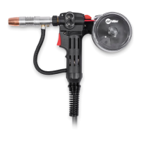
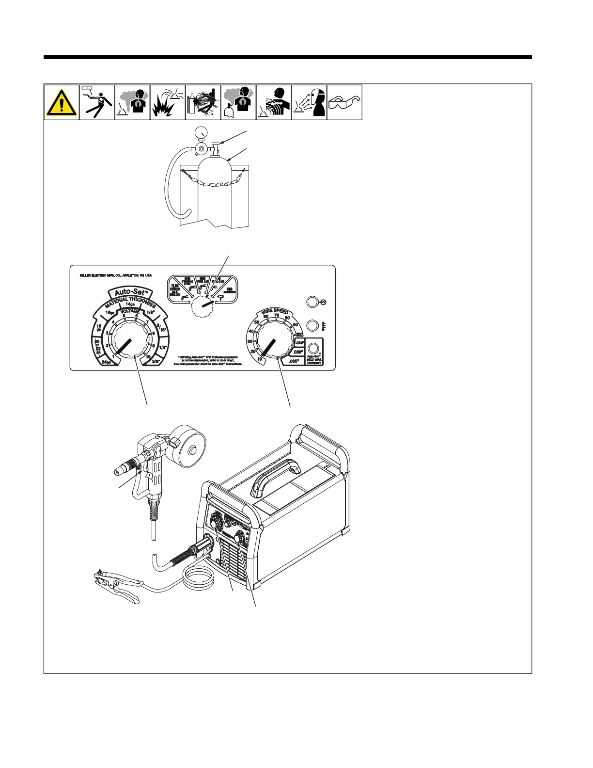
5-1. Controls For Millermatic 211
OM-272 384 Page 4
SECTION 2 OPERATION
2-1. Controls For Millermatic 211
Ref. 265 381-A / Ref. 271 714-A
1
2
3
5
6
6
7
7
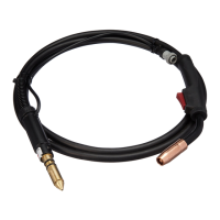
1 Shielding Gas Cylinder
For shielding gas connections, see welding
power source Owner’s Manual.
2 Valve
Open valve on cylinder just before welding.
Close valve on cylinder when finished
welding.
3 Process Select Switch
Select the Spool Gun position.
4 Perform Motor Calibration
See the Millermatic 211 Owner’s Manual for
Spoolmate Motor Calibration procedure.
5 Trigger
Press trigger to energize welding power
source contactor, start shielding gas flow,
and begin wire feed.
6 Wire Feed Speed Control
Wire feed speed is controlled by welding
power source Wire Speed control (see weld-
ing power source Owner’s Manual or door
chart for appropriate setting).
7 Voltage Control
Arc voltage is controlled by welding power
source Voltage control (see welding power
source Owner’s Manual or door chart for ap-
propriate setting).
F
To purge shielding gas line, hold trigger
for three seconds.