OM-272384 Page 18
5-2. Controls For Millermatic 211 Auto-Set
™
Models
OM-272 384 Page 5
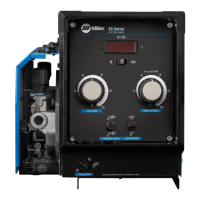
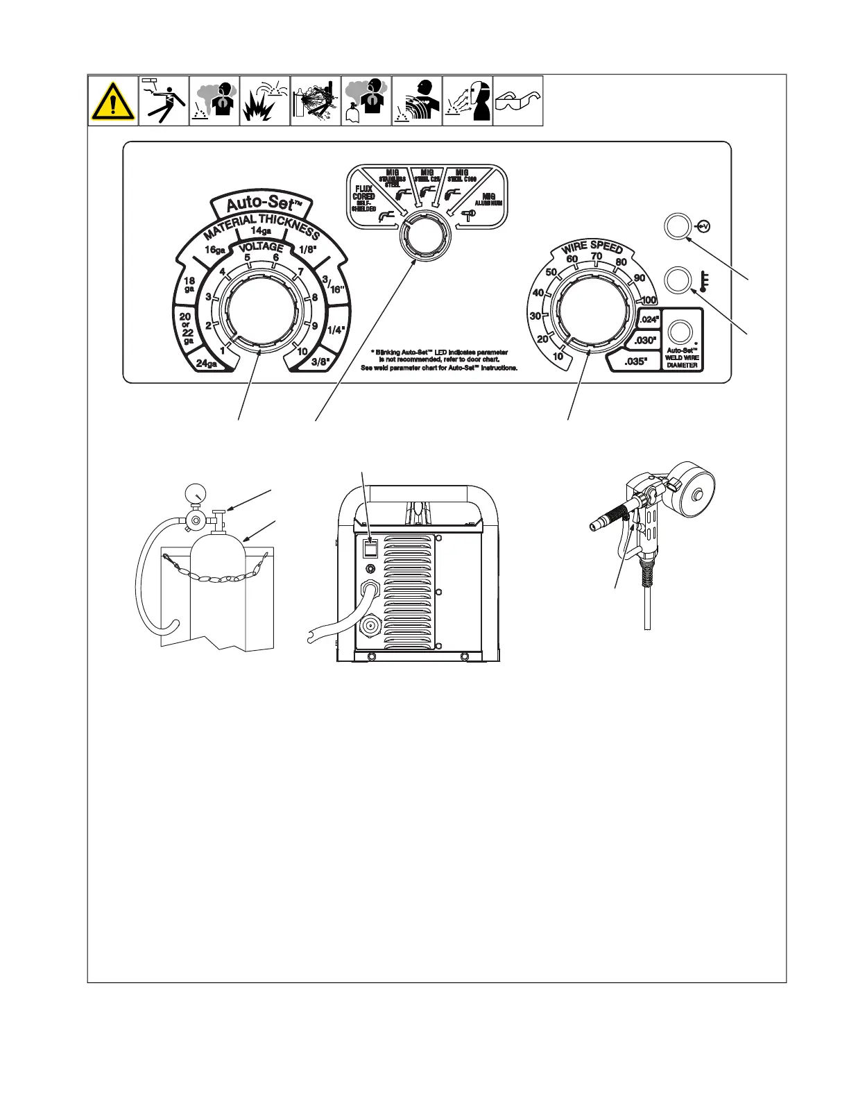
2-2. Controls For Millermatic 211 Auto-Set Models
274604-A / 270208-A
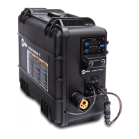
Rear View
6
1
2
4
3
3
7
8
9
10
1 Shielding Gas Cylinder
For shielding gas connections, see welding
power source Owner’s Manual.
2 Valve
Open valve on cylinder just before welding
Close valve on cylinder when finished
welding.
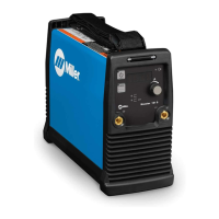
3 Voltage/Material Thickness Control
Turn control clockwise inside white scale (1-
10) to increase voltage (see weld parameter
chart in welding power source).
4 Process Select Control
Turn control to select desired weld process.
5 Perform Motor Calibration
See the Millermatic 211 Owner’s Manual for
Spoolmate Motor Calibration procedure.
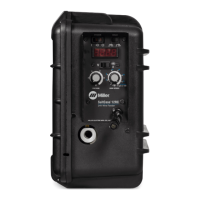
6 Wire Speed/Wire Diameter Control
Turn control clockwise inside white scale
(10-100) to increase wire feed speed. (see
weld parameter chart in welding power
source).
7 Over Temperature Light
If unit overheats, light turns on and output
stops. Allow unit to cool before resuming
operation. This light will also communicate
additional unit errors.
8 Power Light
Power light illuminates when the unit is
turned on and powered up.
9 Power Switch
Use switch to turn unit On or Off.
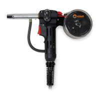
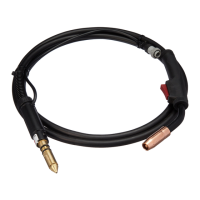
10 Trigger
Press trigger to energize welding power
source contactor, start shielding gas flow,
and begin wire feed.