© 2009 MIMAKI ENGINEERING CO.,LTD.
4.3.5 P.1
1
2
3
4
5
6
7
8
R.1.0
Maintenance Manual > Adjustment Items > Mechanical Adjustment > Positioning of the Encoder Sensor
Model CJV30/TPC Issued 2008.08.04 Revised F/W ver. 1.00 Remark
1.0
4.3.5 Positioning of the Encoder Sensor
Function
Procedure
1. Loosen the screws on the L sensor BKT.
Refer to 6.5.12 Encoder PCB Assy for details concerning its
assembly and disassembly.
2. Adjust the height of the encoder PCB assy and fix it with
screws.
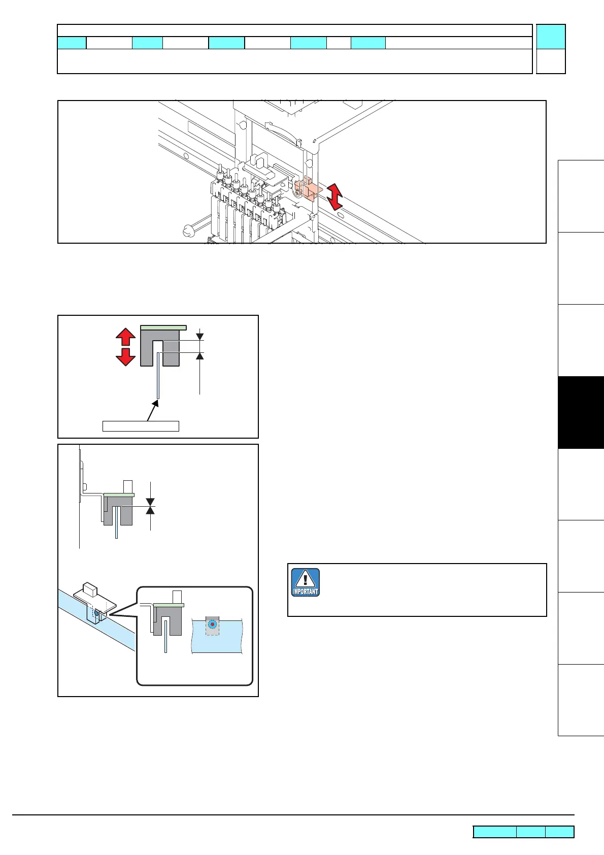
3. Check the following two items when moving the print head carriage
manually from the right end to the left end on the main body.
• The upper part of the linear encoder scale is not in touch
with the L sensor.
• The exposed lens of the L sensor is not over the height of the
linear encoder scale.
NG
The linear encoder scale
must not be in touch with
the L sensor.
The linear encoder scale must
be positioned so that the lens of
the L sensor is hidden by it.
After fixing the L sensor BKT, check whether no
abnormality is found by conducting the following
[#TEST].
• 5.1.26 LINEAR ENCODER

 Loading...


