2-7
2.4.3 Alarm Lamp Board
The alarm lamp board is located at the top of front housing. It has two-color indicators, red and yellow. The alarm
lamp board directly connects the main board through a cable. It is controlled directly by the main board.
2.4.4 Touchscreen and Touchscreen Control Board
The touchscreen control board drives the touchscreen and implements communication with the monitor.
2.4.5 Wi-Fi Module (For Passport 12/Passport 8 Only)
The Wi-Fi module enables the monitor to connect to 802.11 g/n wireless network.
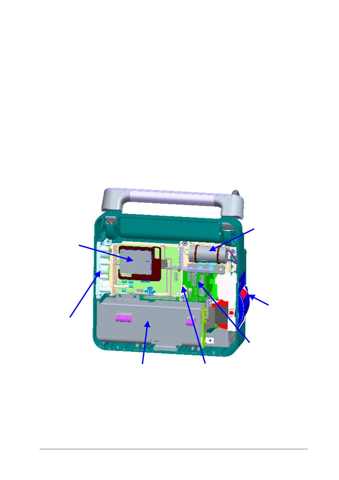
2.5 Rear Housing Assembly
The rear housing assembly consists of the parameter panel assembly, multi-parameter assembly, pump and valve
assembly, recorder assembly, main bracket assembly (including the battery compartment and battery interface board),
power management board, and interface board.
Pump and valve
assembly
Recorder assembly
Interface Board
Power management board
Main bracket assembly
Parameter panel
assembly
Multi-parameter
assembly