Home
Minebea Intec
Measuring Instruments
PR 5310/12
Minebea Intec PR 5310/12 User Manual
5
of 1
of 1 rating
200 pages
Give review
Manual
Specs
To Next Page
To Next Page
To Previous Page
To Previous Page
Loading...
4. Device installation
| 4.3 - Hardware construction
| 63
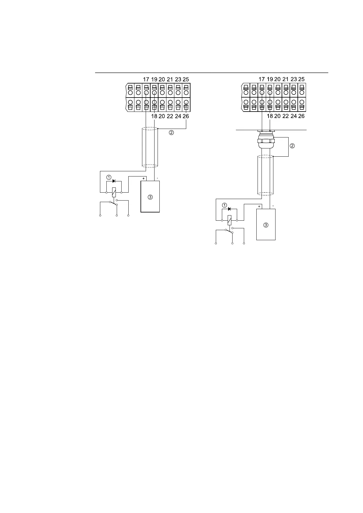
Connection example for relay contr
ol (current output)
Panel device
Table-top device
①
Inductive load for free-wheel diode
②
Screen
③
Power supply unitU
DC
=24V0.5A
The relay switches when the output is active (true).
T
o protect the output circuit, relays must be equipped with free-wheel
diodes.
62
64
Table of Contents
Table of Contents
3
Introduction
7
Read the Safety Instructions and the Manual
7
This Is What Operating Instructions Look Like
7
This Is What Lists Look Like
7
This Is What Warnings Look Like
7
Hotline
8
Safety Instructions
9
General Instructions
9
Intended Use
9
Initial Inspection
9
Before Operational Startup
10
Installation
10
Opening the Device
11
Supply Voltage Connection
12
Protective Ground Connection
13
RF Interference Suppression
14
Failure and Excessive Stress
14
Important Note
14
Repairs and Maintenance
14
Device Description
16
General Information
16
Overview of the Device
16
Communication Protocols
17
Housing
17
Control Panel Housing
17
Indicator Front
21
Overview of Connections
23
Device Installation
28
General Instructions
28
Mechanical Preparation
29
Storage and Transport Conditions
29
Installation Location
29
Unpacking
29
Checking the Equipment Supplied
30
Acclimatizing the Device
30
Cable Gland and Cable Connection
30
EMC-Compliant Installation
33
Hardware Construction
34
Main Board
34
Analog Weighing Electronics Board
35
Connection of Analog Load Cells and Platforms
37
1×RS-232 Interface und 1×RS-485 Interface
48
Digital Inputs and Outputs (3 IN/3 OUT)
58
Analog Output
65
Analog Output & Profibus-DP Interface
67
Profibus-DP Interface
68
Devicenet Interface
73
Ethernet/Ip Interface
78
Profinet I/O Interface
81
Getting Started
85
Switching on the Device
85
Switching off the Device
85
Device Warm-Up Time
85
Power Failure
85
Data Backup
85
Overwrite Protection
86
CAL Switch
86
Performing a Factory Reset on the Device
87
Operating
88
Operating and Display Elements
88
Indicator Display
88
Keypad
89
Selecting Parameters
90
Configuration and Adjustment Via the Keypad
91
Parameter Table (Setup)
91
Date & Time
98
New Adjustment of the Internal Weighing Point
99
Changing the Dead Load of the Internal WP
103
Displaying Adjustment Data of the Internal WP
106
Displaying Adjustment Data for Dead Load and Max
108
Entering Metrology Parameters
109
Limits
113
Configuring Digital Inputs
117
Setting Conditions
120
Configuring Digital Outputs
122
Configuring the Analog Output
126
Entering Operating Parameters
131
Configuring Serial Interfaces
132
Entering Fieldbus Parameters Using Front-Panel Keys
136
Displaying System Information
137
Printing Configuration Data
138
Other Functions Via Keypad
138
Testing the Front-Panel Keys
138
Testing Digital Inputs
139
Testing Digital Outputs
140
Testing the RS-232 Interface
141
Testing the RS-485 Interface
142
Testing the Analog Output
142
Modbus Protocol
144
General Description
144
SMA Protocol
145
General Description
145
Fieldbus Interface
146
General Notes
146
Scale Protocol
146
Data Exchange Range
147
Reading and Writing Data with Function Numbers
151
Reading and Writing Bits Directly
153
Waiting for the Result of the Action
155
Function Numbers
156
Example: Reading the Gross Weight
166
Special Note for Devicenet and Ethernet/Ip
168
0 Spm
169
General Notes
169
0.2 Elementary Data Types
169
Addressing
170
System Data
171
11 Error Messages
174
Error Messages Measuring Circuit
174
General Error Messages
175
Error Numbers @ "LAST_ERROR
177
Weighing Point Errors
177
2 Maintenance/Repairs/Cleaning
178
Maintenance
178
Repairs
178
Battery for Date/Time
178
Replacing the Battery for Date/Time
179
Solder Work
179
Cleaning
179
2.4.1 Instructions for Cleaning
179
3 Safety Inspection
180
4 Disposal
181
5 Specification
182
Equipment Supplied
182
General Technical Data
182
5.2.1 Date/Time Buffer
182
Display
182
5.2.3 Supply Voltage Connection Version 24 V DC
183
Effect of Ambient Conditions
183
5.3.1 Ambient Conditions
183
5.3.2 Electromagnetic Compatibility (EMC)
184
RF Interference Suppression
184
5.4 Weighing Electronics Data
185
5.4.1 Load Cells
185
Principle
185
5.4.3 Accuracy and Stability
186
5.4.4 Sensitivity
186
5.4.5 Connecting Cables
186
Mechanics
187
Housing
187
6 Appendix
188
Order Information
188
6.1.1 Ordering Numbers
188
6.1.2 Order Numbers, for India Only
190
6.1.3 Order Numbers, for China Only
192
Certificates
193
6.2.1 Meu23007
194
Muk23003
199
5
Based on 1 rating
Ask a question
Give review
Questions and Answers:
Need help?
Do you have a question about the Minebea Intec PR 5310/12 and is the answer not in the manual?
Ask a question
Minebea Intec PR 5310/12 Specifications
General
Brand
Minebea Intec
Model
PR 5310/12
Category
Measuring Instruments
Language
English
Related product manuals
Minebea Intec PR 5310
200 pages
Minebea Intec X3
362 pages