(2181) 23
■■
■■
■
Fig. 5Fig. 5
Fig. 5Fig. 5
Fig. 5
■■
■■
■
Fig. 6Fig. 6
Fig. 6Fig. 6
Fig. 6
2162-14792162-1479
2162-14792162-1479
2162-1479
2162-14782162-1478
2162-14782162-1478
2162-1478
2162-14942162-1494
2162-14942162-1494
2162-1494
2162-14702162-1470
2162-14702162-1470
2162-1470
2162-14802162-1480
2162-14802162-1480
2162-1480
■■
■■
■
Fig. 7Fig. 7
Fig. 7Fig. 7
Fig. 7
■■
■■
■
Fig. 8Fig. 8
Fig. 8Fig. 8
Fig. 8
2162-14752162-1475
2162-14752162-1475
2162-1475
2162-14702162-1470
2162-14702162-1470
2162-1470
14991499
14991499
1499
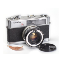
1. Stick #2162-1494 aligning its oval hole to the1. Stick #2162-1494 aligning its oval hole to the
1. Stick #2162-1494 aligning its oval hole to the1. Stick #2162-1494 aligning its oval hole to the
1. Stick #2162-1494 aligning its oval hole to the
groove of #2162-1470/ 1480.groove of #2162-1470/ 1480.
groove of #2162-1470/ 1480.groove of #2162-1470/ 1480.
groove of #2162-1470/ 1480.
2. Fit the projection of #2162-1478/ 1479 to the groove2. Fit the projection of #2162-1478/ 1479 to the groove
2. Fit the projection of #2162-1478/ 1479 to the groove2. Fit the projection of #2162-1478/ 1479 to the groove
2. Fit the projection of #2162-1478/ 1479 to the groove
of #2162-1470/ 1480 to install.of #2162-1470/ 1480 to install.
of #2162-1470/ 1480 to install.of #2162-1470/ 1480 to install.
of #2162-1470/ 1480 to install.
ProjectionProjection
ProjectionProjection
Projection
ProjectionProjection
ProjectionProjection
Projection
Oval holeOval hole
Oval holeOval hole
Oval hole
GrooveGroove
GrooveGroove
Groove
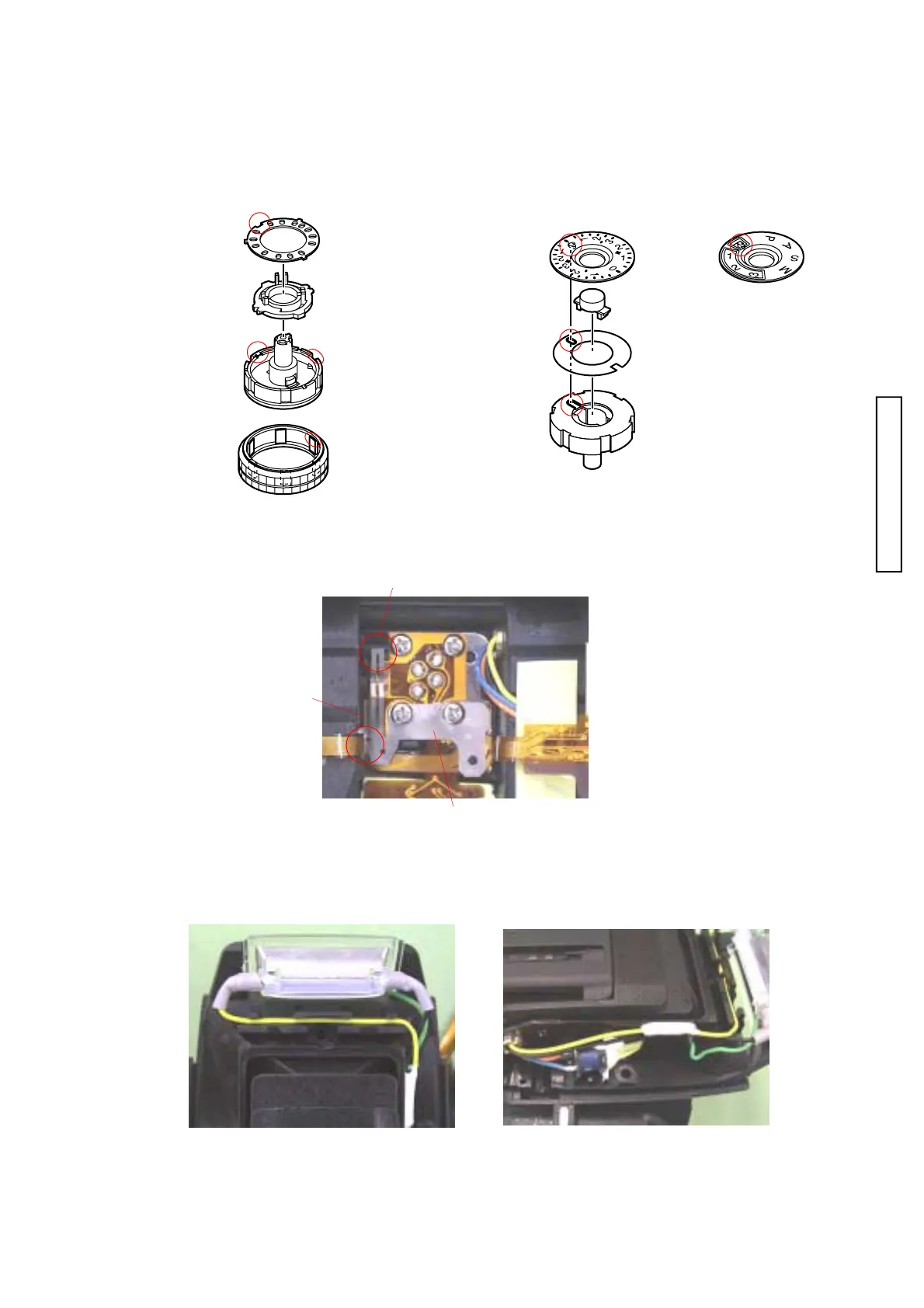
ROTATION AXIS (R)ROTATION AXIS (R)
ROTATION AXIS (R)ROTATION AXIS (R)
ROTATION AXIS (R)
SHOE FIXING PLATESHOE FIXING PLATE
SHOE FIXING PLATESHOE FIXING PLATE
SHOE FIXING PLATE
SFL CONTACTSFL CONTACT
SFL CONTACTSFL CONTACT
SFL CONTACT
Arrange lead wiresArrange lead wires
Arrange lead wiresArrange lead wires
Arrange lead wires
1. Install #2162-1475 to #2162-1470 fitting its1. Install #2162-1475 to #2162-1470 fitting its
1. Install #2162-1475 to #2162-1470 fitting its1. Install #2162-1475 to #2162-1470 fitting its
1. Install #2162-1475 to #2162-1470 fitting its
notch to part-a.notch to part-a.
notch to part-a.notch to part-a.
notch to part-a.
2. Fit #1499 to #2162-1470 aligning its projec-2. Fit #1499 to #2162-1470 aligning its projec-
2. Fit #1499 to #2162-1470 aligning its projec-2. Fit #1499 to #2162-1470 aligning its projec-
2. Fit #1499 to #2162-1470 aligning its projec-
tions to each dent.tions to each dent.
tions to each dent.tions to each dent.
tions to each dent.
NotchNotch
NotchNotch
Notch
DentDent
DentDent
Dent
ProjectionProjection
ProjectionProjection
Projection
Part-aPart-a
Part-aPart-a
Part-a

 Loading...