54 (2181)
REPAIR GUIDE
■■
■■
■
Fig. 1Fig. 1
Fig. 1Fig. 1
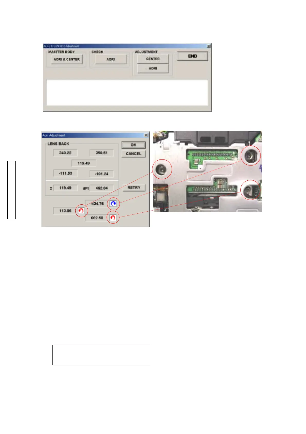
Fig. 1
■■
■■
■
Fig. 2Fig. 2
Fig. 2Fig. 2
Fig. 2
Procedure of CCD AORI checking
1. Click “AORI & CENTER” in adjustment menu.
2. Click MASTER BODY AORI & CENTER in AORI & CENTER Adjustment menu. (Fig. 1)
3. Setting Data of master body has complete! is displayed, then reading Master body data is complete.
4. Click END in AORI & CENTER Adjustment menu.
5. Click ADJUSTMENT END in adjustment menu.
6. Exchange Master camera for target camera.
Be careful to exchange camera to avoid any change to the setting.
7. Set camera to adjustment mode.
Refer to Starting up the 2181 adjustment program (in the adjustment mode) in P. **.
8. Click AORI & CENTER in adjustment menu.
9. Click CHECKAORI in AORI & CENTER Adjustment menu. (Fig. 1)
10. Check the numbers displayed in Aori Adjusment window, whther value ofC and dPI is in the
range of standard value. (Fig. 2)
Standard value of C: From -10 to 10
Standard value of dPI: From -10 to 10
AORI adjusting screwsAORI adjusting screws
AORI adjusting screwsAORI adjusting screws
AORI adjusting screws
Numbers mean the degrees of rotating adjusting screwNumbers mean the degrees of rotating adjusting screw
Numbers mean the degrees of rotating adjusting screwNumbers mean the degrees of rotating adjusting screw
Numbers mean the degrees of rotating adjusting screw
Arrows mean the direction of rotating adjusting screwArrows mean the direction of rotating adjusting screw
Arrows mean the direction of rotating adjusting screwArrows mean the direction of rotating adjusting screw
Arrows mean the direction of rotating adjusting screw

 Loading...