24
Installing Adder Modules
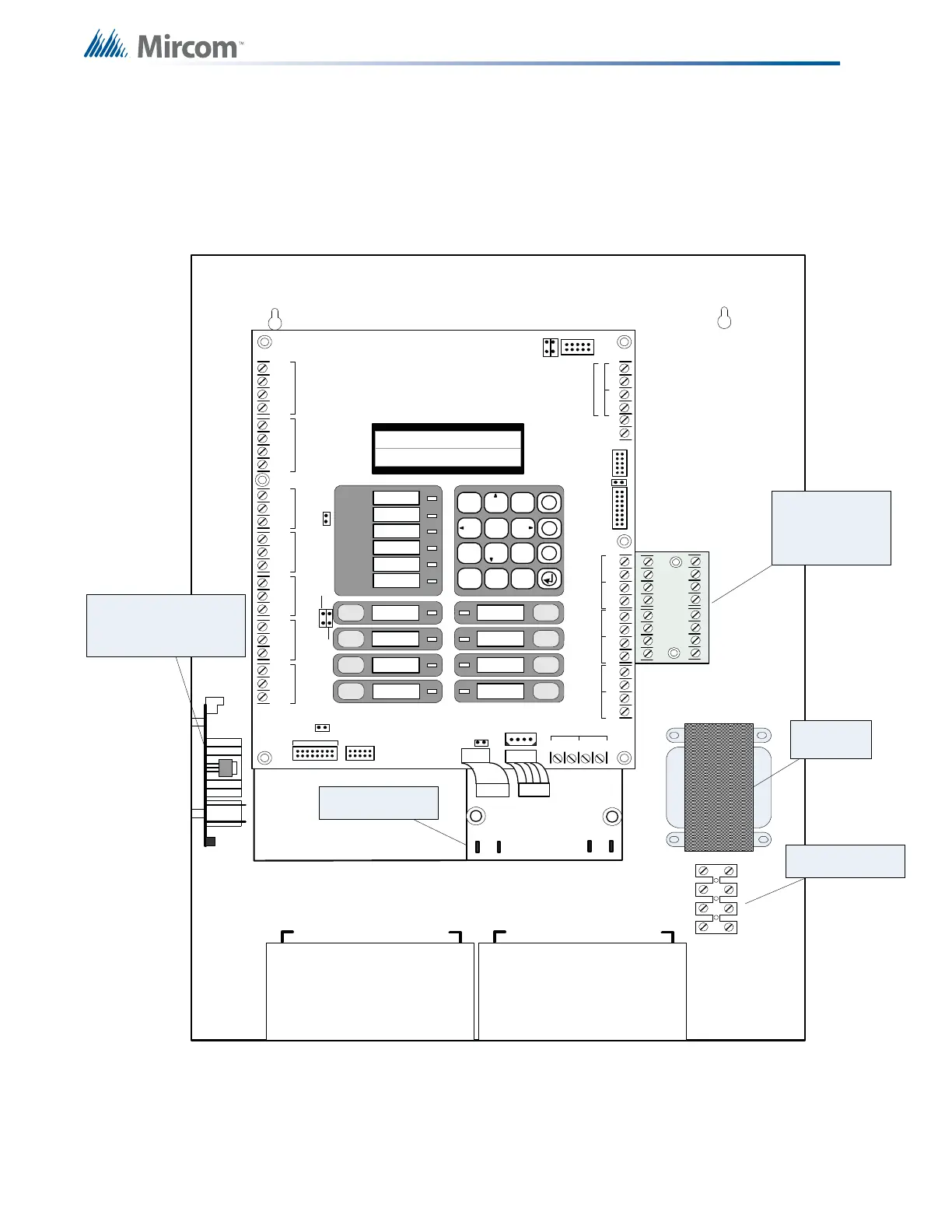
6.0 Installing Adder Modules
The FX-350 Series Fire Alarm panels come pre-assembled with all components and boards
except for Adder Modules. Module installation locations are shown below. Refer to Figure 6
and Figure 7 for Jumper or DIP Switch settings and see Chapter 8.0 Field Wiring on page 31
for wiring specifications.
Figure 6 Installation of Adder Modules
CLASS- A converter
board for indicating
circuits OCAC-304
(4 circuits)
Reverse polarity and city
tie module PR -300 .
Mounted on hex spacer
with two screws provided
Transformer
AC wiring terminal
-SIG
1OUT+-SIG2 OUT+
-SIG1 RET+-SIG2 RET+
BL K
RED
BLK
RED
-SIG3 O
UT+
-SIG4 OUT+
-SIG3 RET+-S IG4 RET +
BLK
RED
BLK
RED
P3
B A TTE RY
P4
+
-
P1
P2
SEC TX
PO WER
SUPPLY
Power supply
board
BATTERY
+-
BATTERY
+-
S-+NC N OCNC NOCNC NOCNC N OC RTRT RT R T
RES CO RES C O
LI NE 1LINE2
JW 7
-+ +-
+--+
-+-+
SI G 1SIG 2SI G 3SI G 4
TO PR-300 MO DULE
RS-485AU X. R ELAY
ALARM
RELA Y
SUPERVISORY
RELAY
TROU BLE
RELAY
AUX
SU P P LY
4-WIRE
SU P P LY
CO M+CO M-TRLTRB
UNFILTERED
FWR24VDC
RTI
PORT
SYSTEM NORMAL
OCT 21 , 2005 02:41AM
Loop
A
+
-
+
-
B
JW 9
JW1
JW3
JW4
SYSTEM
RES ET
FIRE
DRILL
AUTOMATIC ALARM
SIGNAL CANCEL
GENERAL
AL ARM
S IGNAL
SIL ENCE
ALM/SUP/TBL/
BLDG AUDIBLE SIL
LAMP
TEST
SPARE
AC ON
1
2
ABC
3
5 6
7 8 9
*
0 #
4
X
M
?
DEF
GHI JKL MNO
PR S
TU V
WXY
QZ
C OMMON A LAR M
COMMON SUPV
COMMON TROUBLE
CPU FAULT
GROU ND FAU LT
PR- 300 is mounted
here for FX-351
JW 2
JW 6
JW 5
For PC programming use UIMA
Interface module not UL-864 or
ULC-527 listed. Please refer to
Document LT-929 for details
RS-232C PORT
TO RAX-332
P12
P3 P2
4P8P
ALM/SUP/TBL/BLDG
AUDIBLE SIL
 Loading...


