31
Field Wiring
8.0 Field Wiring
8.1 Main Fire Alarm Board Field Wiring
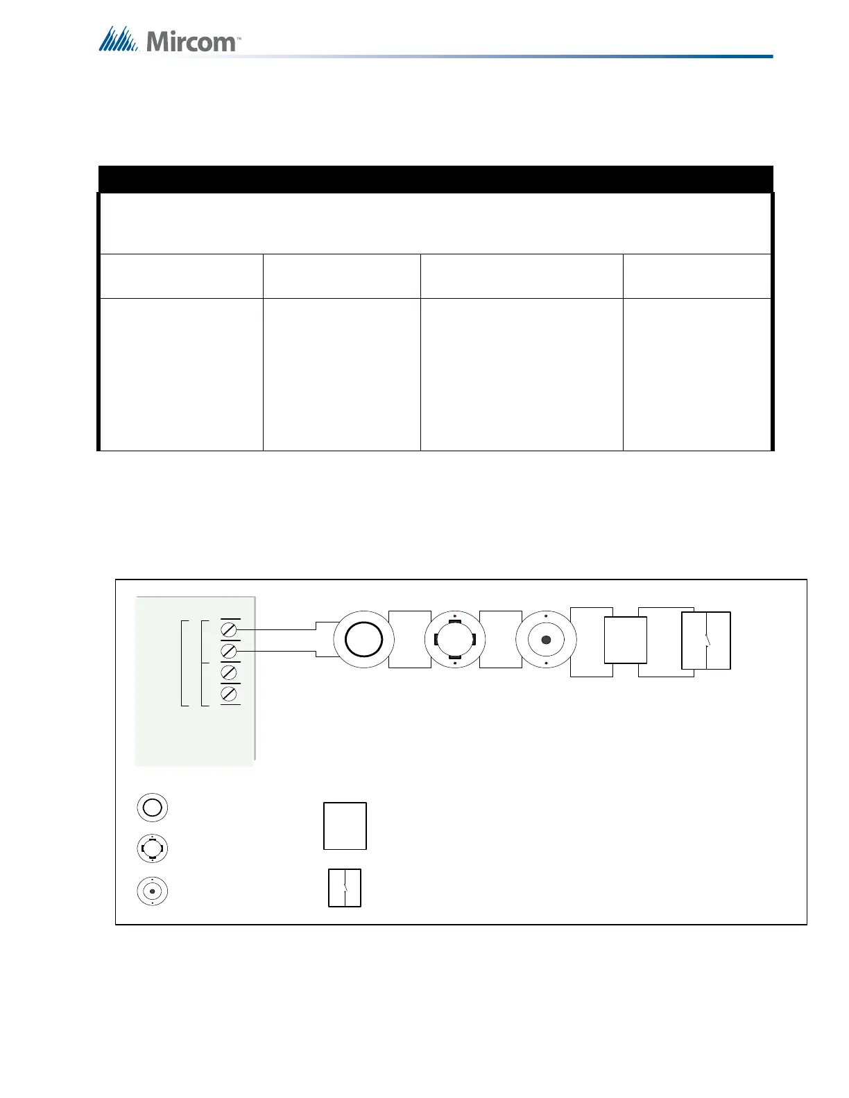
Wire devices to the addressable loop as shown in Figure 11 for Class B (Style 4) or Figure 12
for Class A (Style 6). Refer to Table 3 for loop wire gauges. Wire devices to addressable
loops 2 and 3, if available, in the same manner.
Figure 11 Addressable Loop Wiring - Class B or Style 4
Table 2 Settings permitted in CAN/ULCS527
NOTICE TO USERS, INSTALLERS, AUTHORITIES HAVING JURISDICTION, AND OTHER INVOLVED PARTIES
This product incorporates field-programmable software. In order for the product to comply with the
requirements in CAN/ULCS527, Standard for Control Units for Fire Alarm Systems, certain programming
features or options must be limited to specific values or not used at all as indicated below.
Program feature or
option
Permitted in CAN/
ULCS527? (Y/N)
Possible settings\methods
Settings permitted in
CAN/ULCS527
System Reset and
Signal Silence on RAM-
208/216
N
JW4 (Orange Wire) Intact =
Buzzer silence & Lamp Test
local function only. System
Reset & Signal Silence are
disabled.
Cut Jumper (Orange Wire) to
have all remote functions
operate.
Leave JW4 intact on
RAM-208/216
CLASS B
WIRING
ION SMOKE
DETECTOR
PHOTO SMOKE
DETECTOR
HEAT DETECTOR
PULL STATION
Loop
A
+-+-
B
OUTPUT MODULE
 Loading...


