32
Field Wiring
Table 3 Loop Wiring Table
8.2 Loop Isolators
To limit the number of addressable devices compromised by a short on the addressable loop,
isolators (MIX-100X, 100XH, or 100XB) may be used to isolate the affect of the short circuit. If
the impact of a short circuit must be limited to only one device, an isolating base must be used
for each detector. A maximum of twenty devices can be connected between isolators, or
between the panel and the first isolator, as long as the maximum in-rush current for the
devices on one segment of the loop does not exceed 20 mA. Refer to the installation
instructions for addressable devices for additional details.
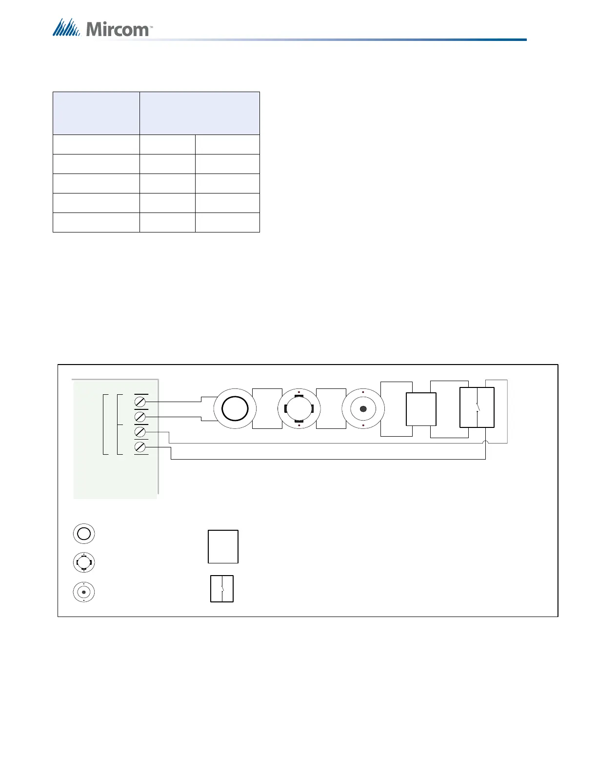
Figure 12 Addressable Loop Wiring - Class A or Style 6
8.3 Loop Operation
When there is a short circuit on the Class A loop with isolators installed, the isolators isolate
the shorted fault, the panel detects it as an open loop and generates an open loop trouble.
UNSHIELDED
TWISTED PAIR
WIRE GAUGE
LOOP TOTAL (OUT
AND IN) WIRE RUN
AWG FEET METRES
12 20,000 6098
14 15,942 4859
16 9960 3036
18 6265 1910
CLASS A
WIRING
ION SMOKE
DETECTOR
PHOTO SMOKE
DETECTOR
HEAT DETECTOR
INPUT MODULE
Loop
A
+-+-
B
OUTPUT MODULE
This Loop Wiring Table is for reference only and should
not be used without a detailed loop calculation.
Maximum Loop Current: 350 mA
Maximum Loop Resistance: 35 subtract 0.2 Ohms per
isolator.
Maximum Loop Capacitance: 0.5 μF
Maximum Number of Isolators is 40.

 Loading...


