64
Appendix D: Power Supply and Battery Calculations
17.0 Appendix D: Power Supply and
Battery Calculations
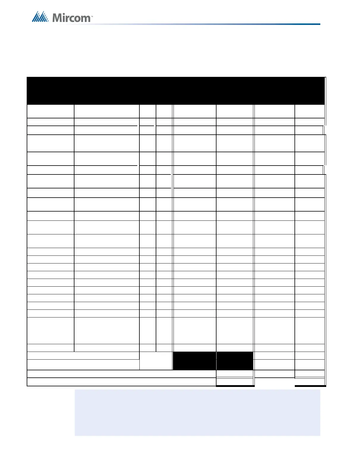
POWER REQUIREMENTS (ALL CURRENTS ARE IN AMPERES)
Model Number Description Qty STANDBY
TOTAL
STANDBY
ALARM
TOTAL
ALARM
FX-350-60-DR Main Panel c/w Dialer X 0.220 = 0.380 =
FX-350-60-D Main Panel c/w Dialer X 0.220 = 0.380 =
FX-351-LW
FX-353-LW
Main Panel c/w 1 RAX-332
LED Displays
X 0.210 = 0.390
(Note 1) =
FX-351-LDW/R
FX-353-LDR
Main Panel, c/w 1 RAX-332
LED Displays and Dialer
X 0.230 = 0.400
(Note 1) =
FX-351-LD Main Panel c/w Dialer X 0.220 = 0.380 =
ALC-252
252 Point Dual Loop
Addressable Adder
x 0.120 = 0.230 =
RAX-332 32 LED Display X 0.005 = 0.010 =
PR-300
Polarity Reversal and City
Tie Module
X 0.050 = 0.300 =
RAM-300-LCDW/R Remote LCD Annunciator X 0.016 = 0.040 =
RAM-208
Remote Annunciator, 8
Zone LED
X 0.0350 = 0.090 =
RAM-216
Ancillary Annunciator, 16
Zone LED
X 0.0350 = 0.140 =
RTI-1 Remote Trouble Indicator X 0.035 = 0.035 =
MIX-3000 Ionization Detector X 0.00028 = 0.00028 =
MIX-3100 Photoelectric Detector X 0.0004 = 0.0034 =
MIX-3200 Multi-sensor Detector X 0.0005 = 0.0035 =
MIX-3300 Heat Detector X 0.0005 = 0.0034 =
MIX-100P Priority Monitor Module X 0.0006 = 0.0046 =
MIX-101P Mini Priority Monitor Module X 0.0006 = 0.0046 =
MIX-100R Relay Output Module X 0.00085 = 0.0035 =
MIX-100S Supervised Control Module X 0.00100 = 0.00100 =
MIX-100X (Kit)
100XH (Isolator)
100XB (Base)
Isolator c/w Mounting Base X 0.000035 = 0.000035 =
MIX-2001R Relay Base X 0.0 = 0.046 =
Device & Remote LEDs (Maximum 30) X
0.0040 =
Signal Load (bells, horns, strobes, and etc.) X
=
Auxiliary Power Supply for Annunciators, etc. (See Note 2) = =
Total currents (Add above currents) STANDBY(A) ALARM (B)
=
Notes: Assumes 25% of Zone LEDS (i.e. 15) are ON during alarm.
See specific installation documentation for standby and alarm currents for other
annunciators listed in Panel Components and Accessories. Observe maximum
auxiliary power supply ratings for lamp test conditions for remote annunciators.

 Loading...


