62
Appendix C: Specifications
16.0 Appendix C: Specifications
16.1 FX-350 Series Specifications
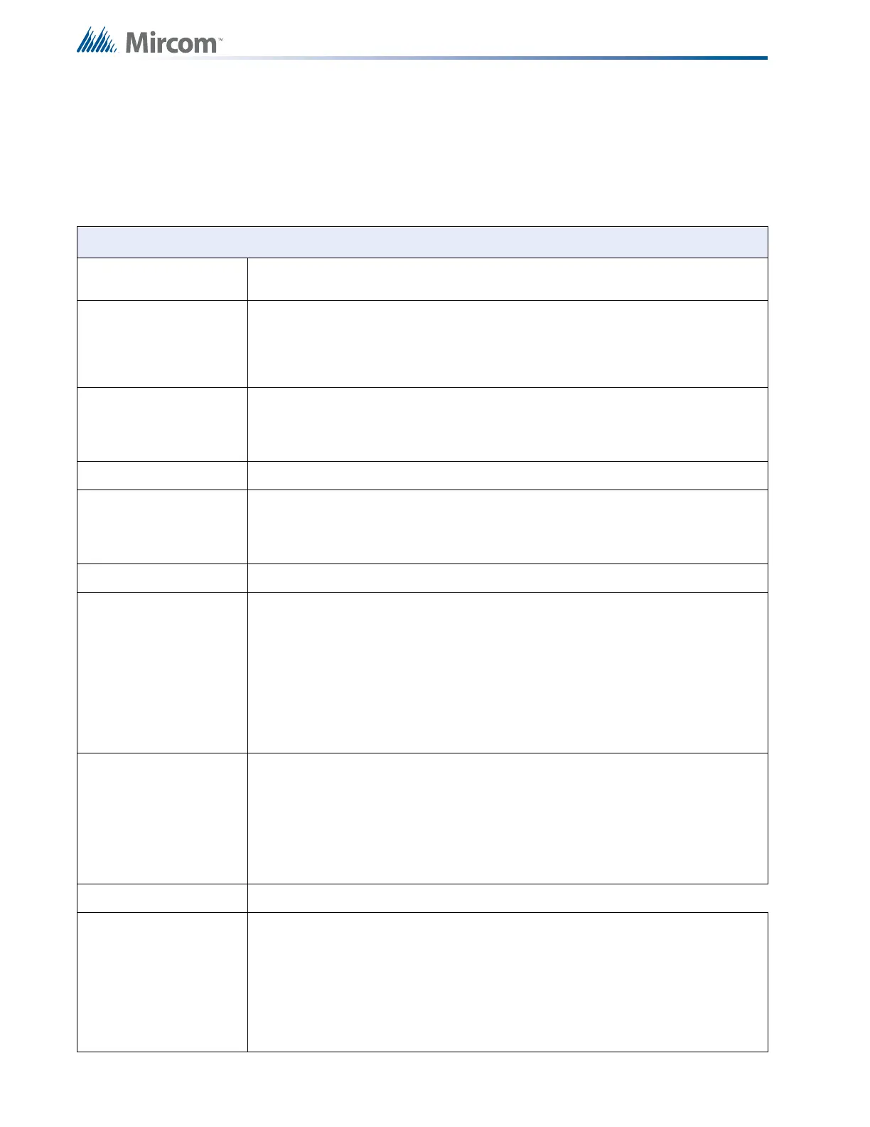
Table 9 FX-350 Series Specifications
FX-350 Series Fire Control Panel Chassis
General
Digital signal processor based design, fully configurable from front panel with password
protection.
Addressable loops
One analog loop capable of addressing 126 Mircom addressable devices, or three analog
loops capable of addressing 378 Mircom addressable devices.
Power Limited / 37VDC / 400mA / maximum loop resistance depends on number of
devices and device type.
Indicating (NAC)
Circuits
4 supervised style Y (Class B) indicating circuits, configured as strobes or audibles.
Terminals are labelled as SIG 1, SIG 2, SIG 3 and SIG 4.
Power limited / Regulated 24VDC FWR / 1.7A @ 49C per circuit
Aux. Supply resettable Power limited / 2
1.1 VDC Filtered regulated / 500mA max
Resettable Auxiliary
Power (Aux 2)
Terminals are labelled 4-WIRE.
Power Limited/21.1 VDC
regulated / 300 mA max.
RS-485 Connection For Remote Annunciators. Terminals are labelled RS485.
Electrical ratings
Power limited / Regulated 24VDC FWR / 1.7A @ 49C per circuit.
Max power allowed • 5A
• 1.7A (aux power unfiltered if used)
• 0.5A (aux power filtered if used)
• 0.3A (resettable auxiliary power if used)
I
f no auxiliaries are used the max power is 5A for the indicating circuits.
Auxiliary relays
(resistive loads)
Must be connected to a listed power limited source of supply. Terminals are
labelled ALARM, TROUBLE, SUPV.
Common alarm Form C, 1 Amp, 28 VDC
Common Supv Form C, 1 Amp, 28 VDC
Common Trouble Form C, 1 Amp, 28 VDC
Unfiltered supply
Power limited / Regulated 24VDC FWR / 1.7A max at 49C
Battery Type 24VDC Gel Cell/Sealed lead acid – 10AH to 24AH
Charging capability 10AH to 24AH
Current Consumption standby: 200 mA
alarm: 350 mA
Protection
10A on board (F1) slow blow micro fuse

 Loading...


