35
Field Wiring
Figure 13 Indicating Circuit – Class B or Style Y Wiring
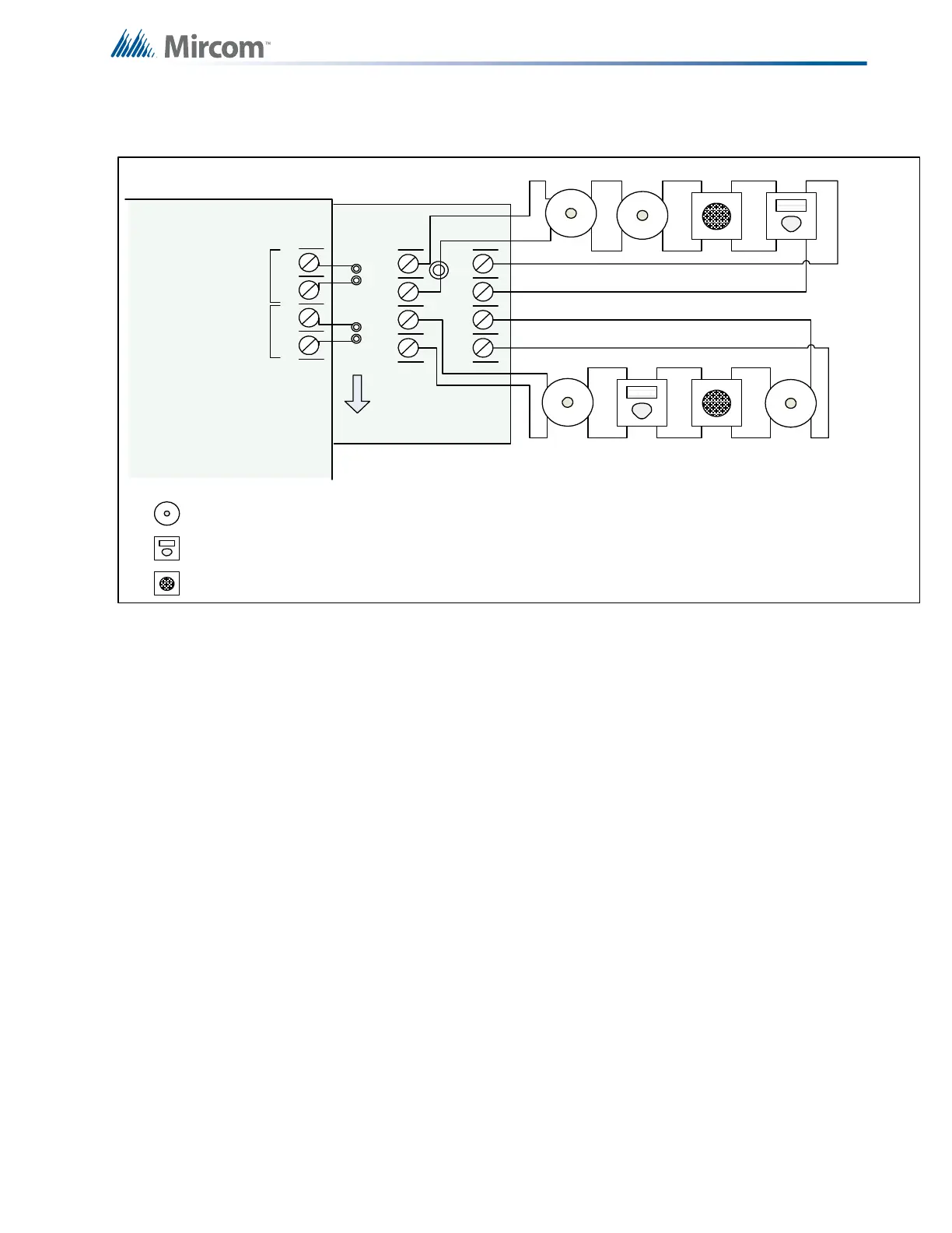
Figure 14 Indicating Circuit –Class A or Style Z Wiring
8.6 Dialer Wiring
If you have Fire Alarm Panel model FX-350-60-DR, FX-350-126-DR, FX-350-378-LDR, FX-
351-LDW or FX-353-DR, there is a dialer on board and terminals marked Line 1 and Line 2
must be wired as shown in Figure 15 below. Terminals are located in the top left hand corner of
BELL
STROBE
HORN
+
-
STYLE Z
WIRING
STYLE Z
WIRING
INDICATING
CIRCUIT #1
INDICATING
CIRCUIT #2
INDICATING
CIRCUIT 1
INDICATING
CIRCUIT 2
2 MORE INDICATING
CIRCUITS NOT SHOWN
OCAC-304 CLASS A
CONVERTER MODULE
FIRE PANEL MAIN BOARD
BLK RED
BLK RED
-
SIG1 OUT+
-
SIG2 OUT+
-SIG1 RET+
-SIG2 RET+
+
-
SIG 1
SIG 2
NOTE: WIRE INDICATING CIRCUITS # 3 AND #4 IN THE SAME WAY
AS #1 AND #2
 Loading...


