34
Field Wiring
0.60 235 71 375 114 600 183 950 289 3
0.90 156 47 250 76 400 122 630 192 2
1.20 118 36 185 56 300 91 470 143 1.5
1.50 94 29 150 46 240 73 380 115 1.2
1.70 78 24 125 38 200 61 315 96 1.0
Notes: For Class A wiring the resistance in ohms is multiplied by two.
Maximum voltage drop should not exceed 1.8 volts.
Table 4 Maximum Wiring Distances
TOTAL
SIGNAL
LOAD
MAXIMUM WIRING RUN TO LAST DEVICE (ELR) MAX. LOOP
RESISTANCE
18AWG 16AWG 14AWG 12AWG
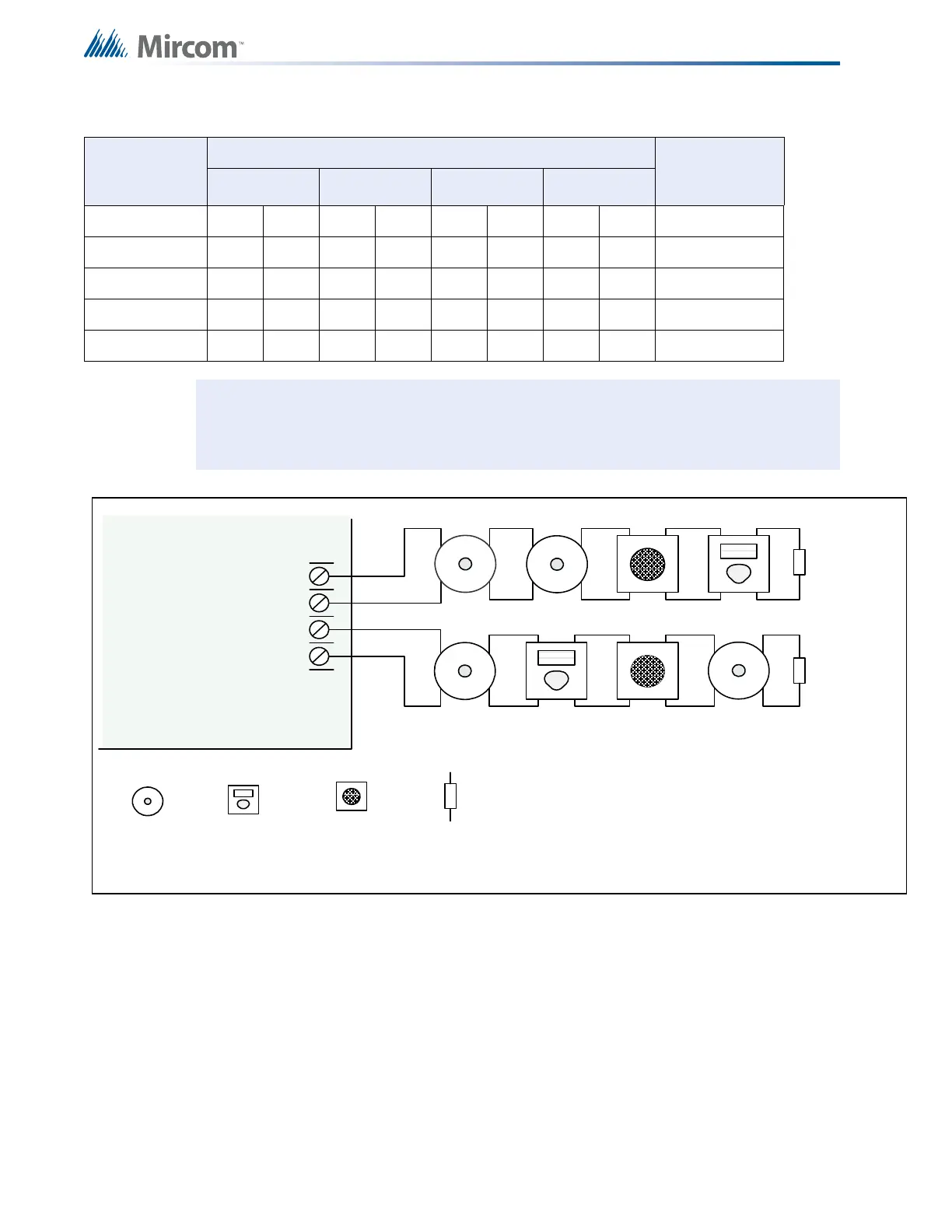
- SIG 1 +
STYLE Y
WIRING
STYLE Y
WIRING
INDICATING
CIRCUIT - 1
INDICATING
CIRCUIT - 2
RLE TTAW 2/1 K9.3EBORTSLLEB
INDICATING
CIRCUIT #1
INDICATING
CIRCUIT #2
HORN
FIRE PANEL MAIN BOARD
- SIG 2 +
NOTE: WIRE INDICATING CIRCUITS # 3 AND #4 IN THE SAME WAY AS
#1 AND #2

 Loading...


