43
Indicators, Controls and Operations
11.0 Indicators, Controls and Operations
Figure 20 below shows the common display panel for both the FX-350, FX-351 and the FX-
353 Fire Alarm Control Panels.
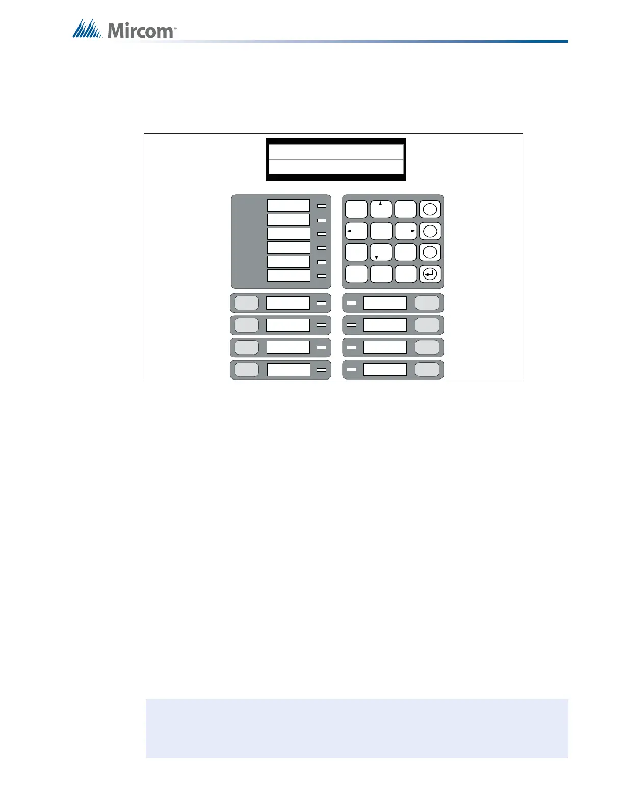
Figure 20 LCD Display, LED indicators and control buttons
The display panel on the FX-350/FX-351/353 main fire alarm control board consists of:
• a two line by twenty character LCD display
• a sixteen button keypad
• common LED Indicators
• common control buttons
FX-351 and FX-353 models are equipped with one RAX-332 LED display adder (32 zone
annunciation), with provision for a second optional adder (see section 4.1 Panel Models on
page 14 for further explanation) for another 32 zone annunciation for a total of 64 zone
annunciation. Each LED zone has a red/amber alarm/supervisory LED and an amber trouble
LED.
LED Indicators may be amber, red, or green, and may illuminate continuously, or at one of
following Flash Rates:
• Steady (Alarm) - ON continuously.
• Fast Flash (Supervisory) - 120 flashes per minute, 50% duty cycle.
• Trouble Flash (Trouble) - 20 flashes per minute, 50% duty cycle.
Red indicators are used for Alarm, amber indicators for Trouble or Supervisory and green for
power ON.
Note: Each RAX-332 display is supplied with blank paper labels (#NP-681) for sliding
into the plastic label template on the display.
COMMON ALARM
COMMON SUPV
TROUBLE
CPU FAULT
GROU ND
FAULT
SYSTEM
RESET
FIRE
DRI LL
AUTOMATIC ALARM
SIGNAL CANCEL
GENERAL
ALARM
S IGNAL
ALM/SUP/TBL/
BLDG AUDIBLE SIL
LAMP
TE S T
BATTERY/CHARGER
AC ON
1 2
ABC
3
DEF
5
JKL
6
MNO
7 8
TUV
9
WXY
* 0
QZ
#
4
GHI
PRS
X
M
?
SYSTEM NORMAL
DEC 03, 2009 02:41AM
COMMON
SILENCE
TROUBLE

 Loading...


