28
Installing Adder Modules
The actual indicating zone is wired from the SIGNAL OUT positive and negative to the
signaling devices and then wired back to the SIGNAL RET positive and negative.
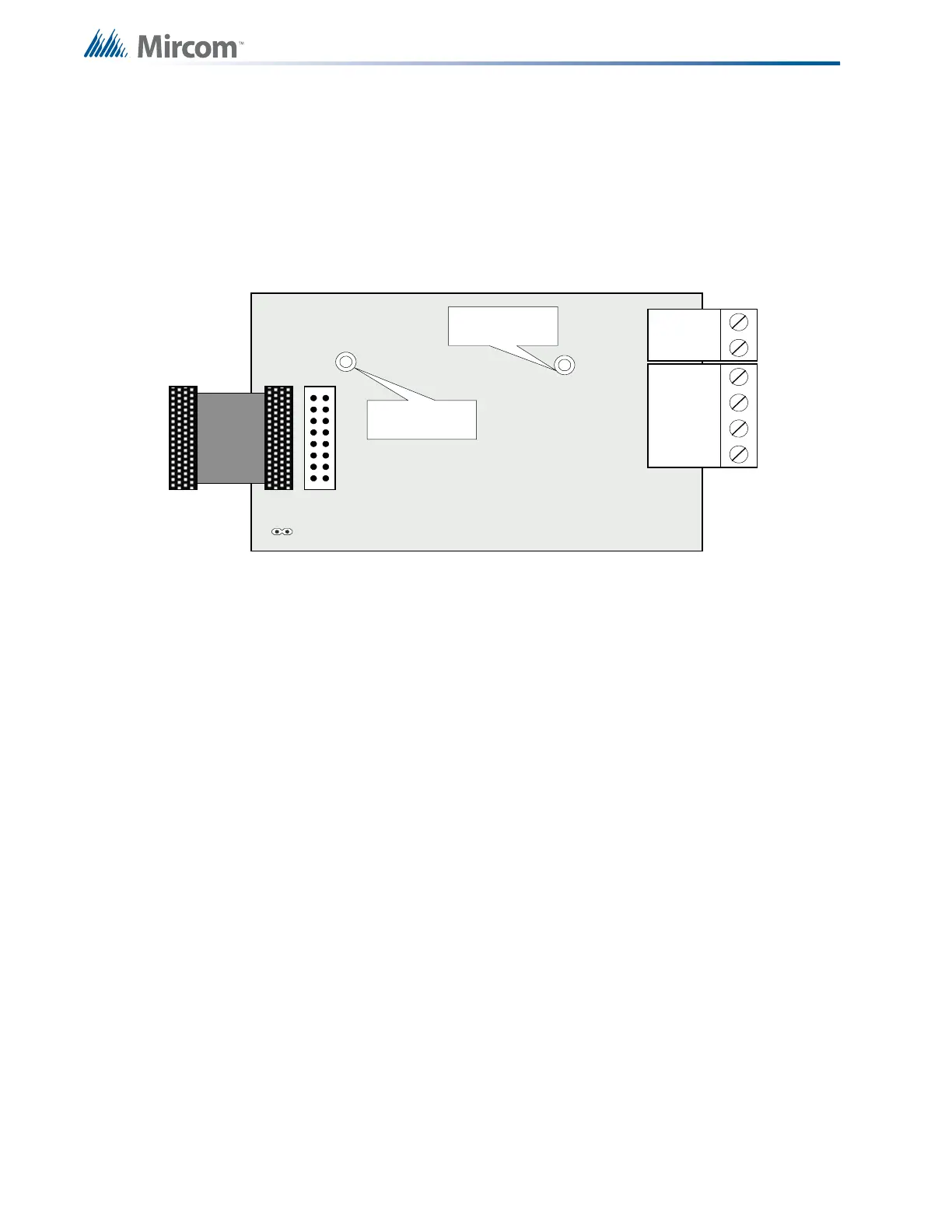
6.4 Polarity Reversal and City Tie Module (Model PR-300)
Mount the PR-300 on the left side panel of the backbox with the two screws provided, refer to
Figure 10.
Figure 10 Polarity Reversal and City Tie Module
6.4.1 PR-300 Cable and Jumper Settings
The following hardware configuration must be performed before installing the PR-300.
The Alarm Transmit signal to the PR-300 can be programmed to turn OFF when signal silence
is active. This allows the City Tie Box to be manually reset. On subsequent alarms the
silenceable signals will resound and the City Tie Box will be retriggered.
The Trouble Transmit signal to the PR-300 can be programmed to delay AC power fail 0, 1, 2,
or 3 hours if this is the only system trouble.
6.5 RAX-332 Display Adder Module
The RAX-332 Display Adder Module is used only with the FX-351 and FX-353 Fire Alarm
Panels. No jumpers or other physical configuration steps are required to install this second
RAX-332 Display Adder Module. Remove the blank cover plate from the front door and install
the RAX-332 with the clear cover in the opening with the hardware provided. Disconnect main
and standby power and connect the cable of the second RAX-332 into the open, remaining
header of the existing RAX-332. The additional LEDs will be available for configuration as
LEDs 33 to 64, when the system power is restored.
P1 Cable connects to P8 (bottom left-hand corner) on the Main Fire Alarm
Board.
JW4 Not used. Keep jumper intact.
POLAR ITY
REVER SAL
ALAR M
POLAR ITY
REVER SAL
SUPV
CITY
TIE
+ | - + | - + | -
JW4
P1 P2
Mounting hole for
#6 -32 screws
Mounting hole for
# 6-32 screws

 Loading...


