5Functions set with parameters
Interference avoidance function 6-527
Each parameter is explained in the following section.
(1) Simulated component registration parameter
Parameters listed in Table 5-30 are explained in detail in this section.
Up to eight simulated component types can be registered for each of the robot arm, hand and workpiece.
The last digit of a parameter name indicates the simulated component type.
1) Simulated components for robot arm
<1> Registration section and shape of simulated components: CAVKDA1 to 8
Table 5-31:Simulated component setting parameter (robot arm: CAVKDA1 to 8)
Center position Using the robot arm installation
face or the rotation center of
each axis as the reference point,
set the simulated component’s
center position as a distance
from that reference point.
Parameters: CAVPSA1 to 8
Designate the simulated component’s center as a distance from the
Mechanical interface coordinate system‘s origin point (tip of J3 axis).
Parameters: CAVPSH1 to 8 Parameters: CAVPSW1 to 8
Simulated component
size
Set the size of each simulated component as a radius.
Parameters: CAVSZA1 to 8 Parameters: CAVSZH1 to 8 Parameters: CAVSZW1 to 8
Enable/disable for each
simulated component
Set whether to enable/disable a simulated component, and whether to temporarily disable a simulated
component when T/B is enabled.
Note) The simulated hand and workpiece must be disabled during teaching.
Parameters: CAVSCA1 to 8 Parameters: CAVSCH to 8 Parameters: CAVSCW1 to 8
Note1) The initial settings for each model are set at the factory.
Parameter
Parameter
name
No. of arrays
No. of characters
Details explanation Factory setting
Registration
section and
shape of sim-
ulated compo-
nent
(robot arm)
CAVKDA1 to 8 Integer 2 Set the registration section (Jn axis) and shape
of a simulated component. Up to eight simulated
component types can be registered. (Each type
corresponds to the last digit (1 to 8) of the
parameter name.)
1st element: Registration section (Jn axis)
0: Base section
1 to 6: Jn axis
2nd element: Shape
0: a sphere
1: a cylinder
Note) The shape of a simulated component is a
sphere.
RH-3/6/12/20FH
series:
CAVKDA1=0, 1
CAVKDA2=0, 0
CAVKDA3=1, 0
CAVKDA4=2, 0
CAVKDA5=2, 0
CAVKDA6=2, 0
CAVKDA7=2, 0
CAVKDA8=4, 1
Note) The setting
value of RH-
3FH35xx, and
RH-6FH35xx and
RH-12FH55xx is
CAVKDA3=0,0.
RH-3FHR series
CAVKDA1=0, 0
CAVKDA2=1, 1
CAVKDA3=1, 0
CAVKDA4=2, 1
CAVKDA5=2, 1
CAVKDA6=3, 1
CAVKDA7=0, 0
CAVKDA8=0, 0
RV-F series:
CAVKDA1=0, 0
CAVKDA2=0, 1
CAVKDA3=2, 1
CAVKDA4=4, 1
CAVKDA5=5, 0
CAVKDA6=0, 0
CAVKDA7=0, 0
CAVKDA8=0, 0
Note) The setting
value of RV-2F is
CAVKDA2=0,0
CAVKDA4=3,0
CAVKDA5=4,1
CAVKDA6=5,0.
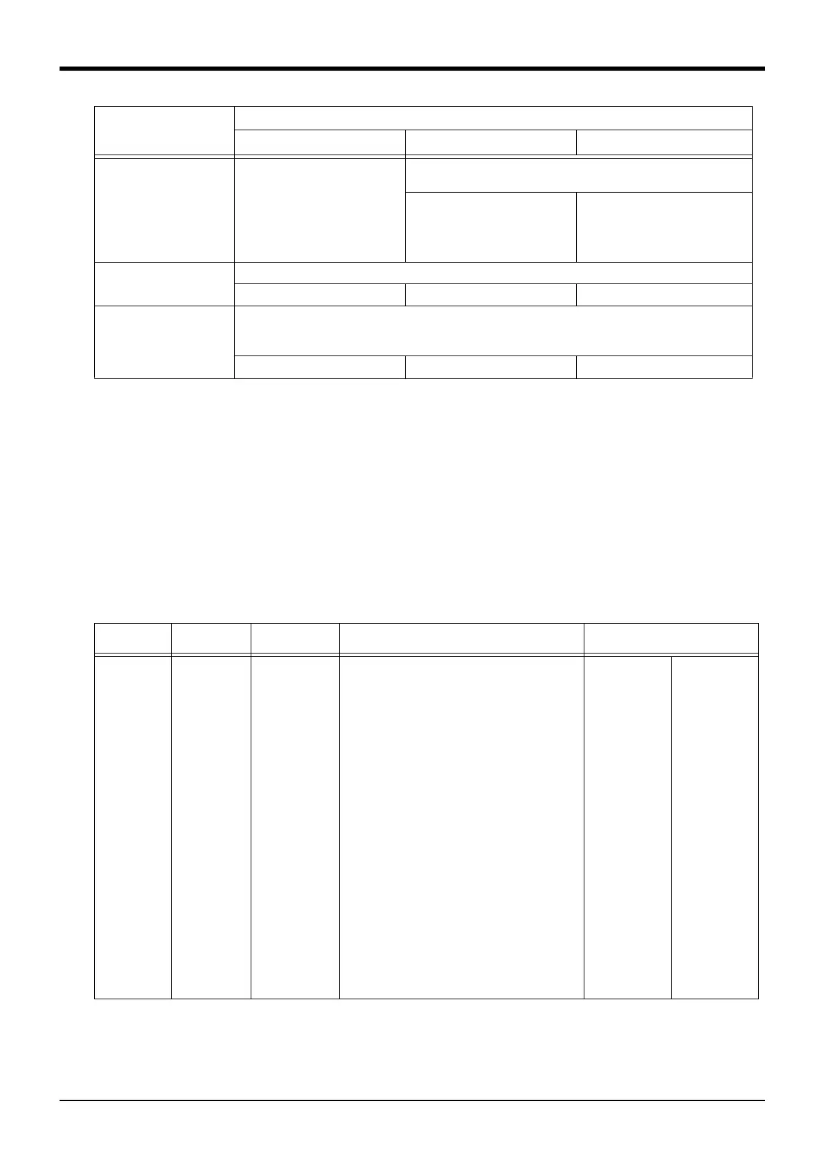
Setting items for
simulated component
Simulated component type
Simulated robot arm
Note1)
Simulated hand Simulated workpiece
 Loading...