6-532 Interference avoidance function
5Functions set with parameters
<4>Simulated component enable/disable: CAVSCA1 to 8
Table 5-34:Simulated component setting parameter (Robot arm: CAVSCA1 to 8)
2) Simulated components for hand
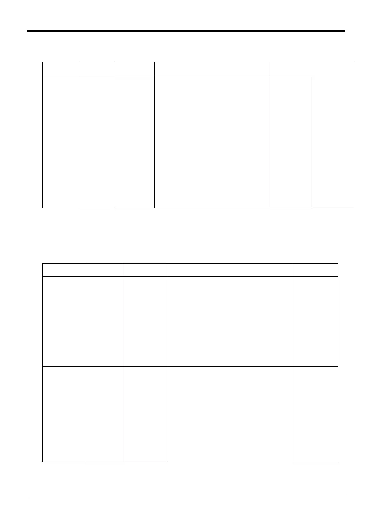
The parameters required to register a simulated hand are shown in Table 5-35.
Table 5-35:Simulated component setting parameters (hand)
Parameter
Parameter
name
No. of arrays
No. of characters
Details explanation Factory setting
Simulated
component
enable/disable
(robot arm)
CAVSCA1 to 8 Integer 3 Set whether to check (enable or disable)
interference for each simulated component. (Each
simulated component corresponds to the last digit
(1 to 8) of the parameter name.)
1st element: Enable/disable the setting
(0: Disable, 1: Enable)
2nd element: Set whether to let the interference
avoidance function to temporarily
disable interference checks during
jog operation. (Refer to Temporarily
canceling the interference avoidance
function.)
(0: Disable, 1: Maintain enabled
state)
Note) If interference is inevitable
during jog operation for
teaching, setting the simulated
hand or workpiece to “0:
Disable” can be convenient.
3rd element: Fixed to 0
RH-3/6/12/20FH
series:
CAVSCA1=1, 0, 0
CAVSCA2=0, 0, 0
CAVSCA3=1, 0, 0
CAVSCA4=1, 0, 0
CAVSCA5=1, 0, 0
CAVSCA6=1, 0, 0
CAVSCA7=1, 0, 0
CAVSCA8=1, 0, 0
RH-3FHR series
CAVSCA1=1, 0, 0
CAVSCA2=1, 0, 0
CAVSCA3=1, 0, 0
CAVSCA4=1, 0, 0
CAVSCA5=1, 0, 0
CAVSCA6=1, 0, 0
CAVSCA7=0, 0, 0
CAVSCA8=0, 0, 0
RV-F series:
CAVSCA1=1, 0, 0
CAVSCA2=1, 0, 0
CAVSCA3=1, 0, 0
CAVSCA4=1, 0, 0
CAVSCA5=1, 0, 0
CAVSCA6=0, 0, 0
CAVSCA7=0, 0, 0
CAVSCA8=0, 0, 0
Parameter
Parameter
name
No. of arrays
No. of characters
Details explanation Factory setting
Hand number and
shape
(hand)
CAVKDH1 to 8 Integer 2 Set the hand number and shape of a simulated hand to
be registered. Up to eight simulated hand types can be
registered. (Each type corresponds to the last digit (1 to
8) of the parameter name.)
1st element: Hand number
Corresponds to the hand condition number
for changing the simulated component with
the Loadset (Load Set) command.
0: Simulated component type set as default.
1 to 8: Hand condition number designated with the
Loadset (Load Set) command
2nd element: Shape
0: a sphere
1: a cylinder
Set all parameters
(CAVKDH1 to 8) to
“0, 0”.
Center position of
simulated compo-
nent
(hand)
CAVPSH1 to 8 Real number 6 For each simulated component, designate the center
position and pose of the simulated component from the
origin point of the Mechanical interface coordinate
system. (Each simulated component corresponds to the
last digit (1 to 8) of the parameter name.)
1st element: Distance in X axis direction (mm)
2nd element: Distance in Y axis direction (mm)
3rd element: Distance in Z axis direction (mm)
4th element: angle of rotation on X axis (degree)
5th element: angle of rotation on Y axis (degree)
6th element: angle of rotation on Z axis (degree)
Note) Calculate the rotation angle in order of Z → Y → X
axis. If shape is the sphere, setting of the rotation
angle is unnecessary.
Set all parameters
(CAVPSH1 to 8) to
“0, 0, 0, 0, 0, 0”.

 Loading...


