4 TEMPERATURE INPUT MODULE REPLACEMENT
4 - 8
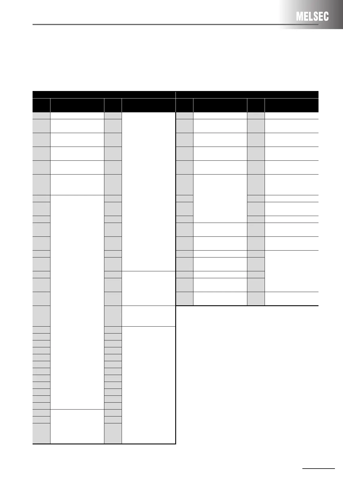
4.2.3 I/O signal comparison to programmable controller CPU
Sequence program change is required as the I/O signals differ.
For details of the I/O signals and sequence program, refer to the Thermocouple Input Module/Channel
Isolated Thermocouple/Micro Voltage Input Module User's Manual.
A616TD Q64TD
Device
No.
Signal name
Device
No.
Signal name
Device
No.
Signal name
Device
No.
Signal name
X0 Watchdog timer error Y0
Not used
X0 Module READY Y0 Not used
X1 A/D conversion READY Y1 X1
CH1 Offset/gain setting
status signal
Y1
CH1 Offset setting
request
X2 Error flag Y2 X2
CH2 Offset/gain setting
status signal
Y2 CH1 Gain setting request
X3
Disconnection error
detection
Y3 X3
CH3 Offset/gain setting
status signal
Y3
CH2 Offset setting
request
X4
Digital output value out-
of-range detection
Y4 X4
CH4 Offset/gain setting
status signal
Y4 CH2 Gain setting request
X5
Detected temperature
value out-of-range
detection
Y5 X5
Not used
Y5
CH3 Offset setting
request
X6
Not used
Y6 X6 Y6 CH3 Gain setting request
X7 Y7 X7 Y7
CH4 Offset setting
request
X8 Y8 X8 Y8 CH4 Gain setting request
X9 Y9 X9
Operating condition
setting completion signal
Y9
Operating condition
setting request
XA YA XA
Offset/gain setting mode
status flag
YA User range write request
XB YB XB Not used YB
Not used
XC YC XC
Disconnection detection
signal
YC
XD YD Interlock signal for the
RFRP and RTOP
instructions when the
A616TD is used in
remote I/O station
XD Warning output signal YD
XE YE XE
Conversion completion
flag
YE
XF YF XF Error flag YF Error clear request
X10 Y10
Detected temperature
value LED display
request signal
X11 Y11
Not used
X12 Y12
X13 Y13
X14 Y14
X15 Y15
X16 Y16
X17 Y17
X18 Y18
X19 Y19
X1A Y1A
X1B Y1B
X1C Y1C
X1D Interlock signal for the
RFRP and RTOP
instructions when the
A616TD is used in
remote I/O station
Y1D
X1E Y1E
X1F Y1F

 Loading...


