7 POSITIONING MODULE REPLACEMENT
7 - 28
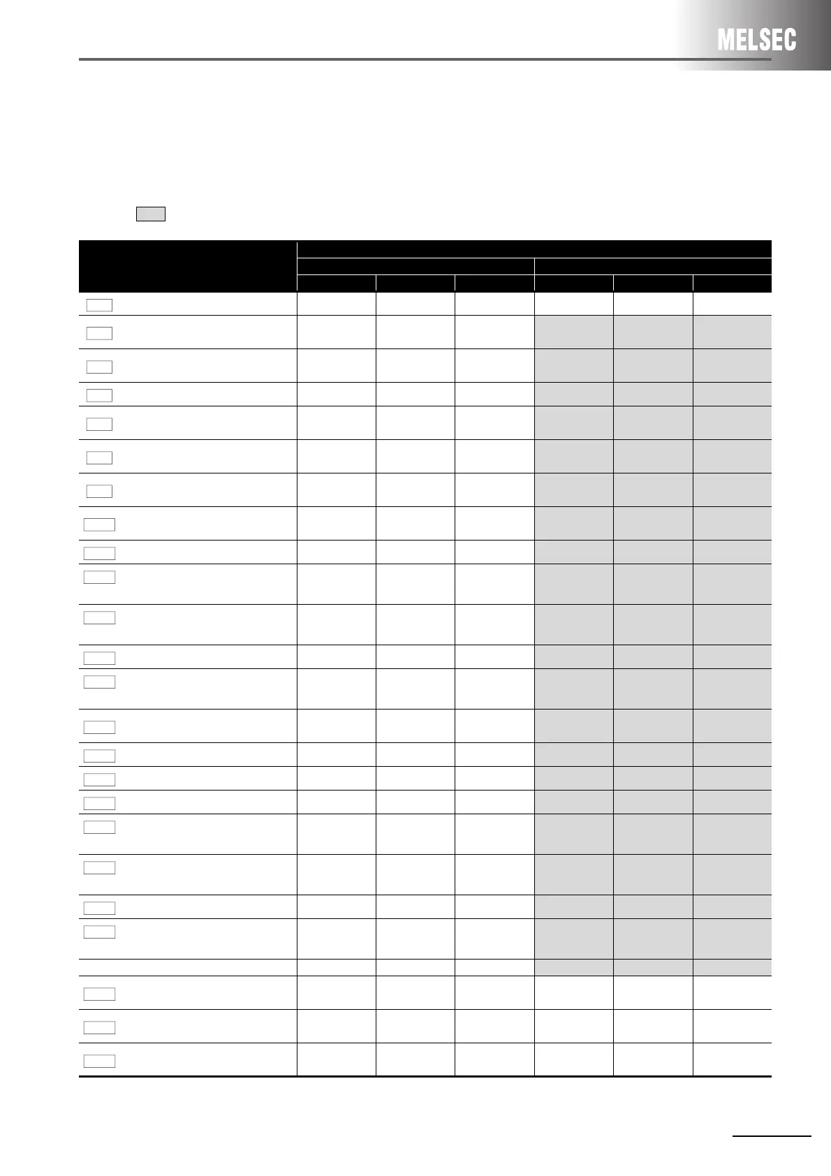
7.5.4 Buffer memory address comparison
Sequence program change is required as the assignment of buffer memory differs.
For details of the buffer memory or sequence program, refer to the Type QD75M Positioning Module
User's Manual.
area shows the differences between AD75M and QD75M.
Item of AD75M
Buffer memory address
AD75M QD75M
Axis 1 Axis 2 Axis 3 Axis 1 Axis 2 Axis 3
Unit setting
0 150
300 0 150 300
No. of pulses per rotation (AP)
1 151
301
2
3
152
153
302
303
Movement amount per rotation (AL)
2 152
302
4
5
154
155
304
305
Unit magnification (AM)
3 153
303 1 151 301
Speed limit value
6
7
156
157
306
307
10
11
160
161
310
311
Acceleration time 0
8
9
158
159
308
309
12
13
162
163
312
311
Deceleration time 0
10
11
160
161
310
311
14
15
164
165
314
315
Bias speed at start
12
13
162
163
312
313
6
7
156
157
306
307
Backlash compensation amount
15 165
315 17 167 317
Software stroke limit upper limit
value
16
17
166
167
316
317
18
19
168
169
318
319
Software stroke limit lower limit
value
18
19
168
169
318
319
20
21
170
171
320
321
Software stroke limit selection
20 170
320 22 172 322
Software stroke limit valid/invalid
setting
21 171
321 23 173 323
Command in-position width
22
23
172
173
322
323
24
25
174
175
324
325
Torque limit setting value
24 174
324 26 176 326
M code ON signal output timing
25 175
325 27 177 327
Speed switching mode
26 176
326 28 178 328
Interpolation speed designation
method
27 177
327 29 179 329
Current feed value during speed
control
28 178
328 30 180 330
Manual pulse generator selection
29 179
329 33 - -
Size selection for acceleration/
deceleration time
31 181
331 - - -
Function selection for speed-positioning - - - 34 184 334
Acceleration time 1
36
37
186
187
336
337
36
37
186
187
336
337
Acceleration time 2
38
39
188
189
338
339
38
39
188
189
338
339
Acceleration time 3
40
41
190
191
340
341
40
41
190
191
340
341
Pr.10

 Loading...


