7 POSITIONING MODULE REPLACEMENT
7 - 47
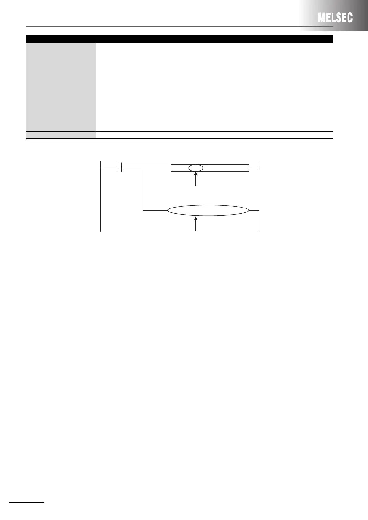
*1 Example of an additional program (using a buffer memory address for the speed change function)
*2 Details of LEDs are shown in the table below.
Mode switch
•AD70
The setting is configured with slide switches or encoder interface setting pin (hardware setting)
1) Slide switches
Rotation direction, accumulated pulse, multiplication setting, zero-return direction, zero-return mode, and
zero/gain adjustment mode setting/clear
2) Encoder interface setting pin
Encoder output types
• QD73A1
The setting is configured with Switch setting in I/O assignment of PLC parameter (GX Developer).
When using GX Works2, set it with the intelligent function module switch setting.)
* Though the setting method is changed from a hardware switch to parameters of software, the same
level of settings are available because the function is upward compatible.
LED Refer to *2.
Changed function Change description
Change command
DTOP
TOP
* Change into "H1" due to change of
the number of occpied slots.
H1 K80 D0 K1
H1 K91 K1 K1
* Create the above due to the speed demand.

 Loading...


