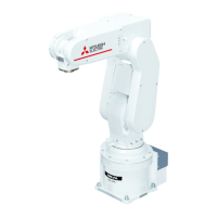
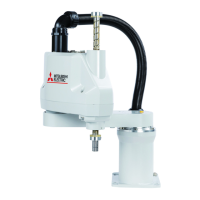
Mounting place for tooling machine, etc.
Installation reference 82
6-M4 screw, depth 8
(for tooling installation)
4-φ7 installation hole
M5 screw, depth 6, φ3 hole drill
φ6h7
φ8
φ18
95
107
34 120
4-φ5 hole
(installation hole)
22
R
3
0
.
5
2
4
.
5
36 (162)
6
5.5
5
10
12
4
5
198
Tooling wiring lead port
4-M4 screw, depth 6
(Installation screw
for tooling support, etc.)
R
3
0
.
5
R
3
0
.
5
5
6
2
8
(
5
6
)
1
4
0
R3
0
.
5
2
4
.
5
5
6
(
5
6
)
6
1
2
8
32
80
Installation reference 38
1
0
0
56
133
150
162
2000
120
140
180 24.2
224.9
155
165
31
9585
17724
31
Z stroke 30
21
30
A
B
8
230
180
77.6
Min. 35
(φ8)
(φ18)
5.5
5.5
View from A (L cut)
M6 screw
Connector box
48 76
Pin hole φ4H7
drill (2 places)
View from B
(Note)
(Note) ・Install the connector box
separately.
・A backup battery is located
inside, so install at an
easy to service place.
The dimensions shown in
parentheses are for the robot arm's
stopper section, and must not be used.
The dimensions are provided for reference.
1
4
0
1
0
0
6.3a
6.3a

 Loading...


