Hand output cable 1A-GR200-RP
(Included in optional solenoid valve set.)
Connector box
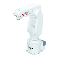
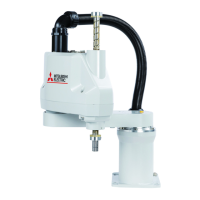
Robot arm
Hand 1
Hand 2
Hand 3
Hand 4
<HC 1>
<HC 2>
<HC 3>
<HC 4>
<HC 5>
<HC 6>
<HC 7>
<HC 8>
<+24V>
<GND>
ON
OFF
ON
OFF
ON
OFF
ON
OFF
Secondary piping pneumatic hoses
φ
4 x 2 to 8
(Prepared by customer)
Primary piping pneumatic hoses
φ
6 x 1
(Prepared by customer)
Solenoid valve set
(optional)
1A-VD04-RP
General-purpose output 900
General-purpose output 901
General-purpose output 902
General-purpose output 903
General-purpose output 904
General-purpose output 905
General-purpose output 906
General-purpose output 907
+24V
Hand input cable
1 A-HC200-RP
General-purpose input 900
General-purpose input 901
General-purpose input 902
General-purpose input 903
General-purpose input 904
General-purpose input 905
General-purpose input 906
General-purpose input 907
+24V
0V(COM)
Hand
prepared
by customer
Robot controller
Wiring relay boad of the robot arm
White
Black
White
Black
White
Black
White
Black
White
<GR 1>
<GR 2>
<GR 3>
<GR 4>
<GR 5>
<GR 6>
<GR 7>
<GR 8>
<+24V>
1
2
3
4
5
6
7
8
9
1
2
3
4
5
6
7
8
9
10
Brown
Red
Orange
Yellow
Green
Blue
Purple
Gray
White
Black
Gray:red 1 dot line
Gray:brack 1 dot line
Gray:red 2 dot line
Gray:brack 2 dot line
Gray:red 3 dot line
Gray:brack 3 dot line
Gray:red 4 dot line
Gray:brack 4 dot line
Gray:red continuas dots line
Gray:brack continuas dots line
Orange:red 1 dot line
Orange:brack 1 dot line
Orange:red 2 dot line
Orange:brack 2 dot line
Orange:red 3 dot line
Orange:brack 3 dot line
Orange:red 4 dot line
Orange:brack 4 dot line
Orange:red continuas dots line
Orange:brack continuas dots line

 Loading...


