6 - 51
CHAPTER6 FUNCTIONS
1
2
3
4
5
6
7
8
6.11 Monitor Function
6.11.3 External input/output forced on/off
(e) External input/output forced on/off timing
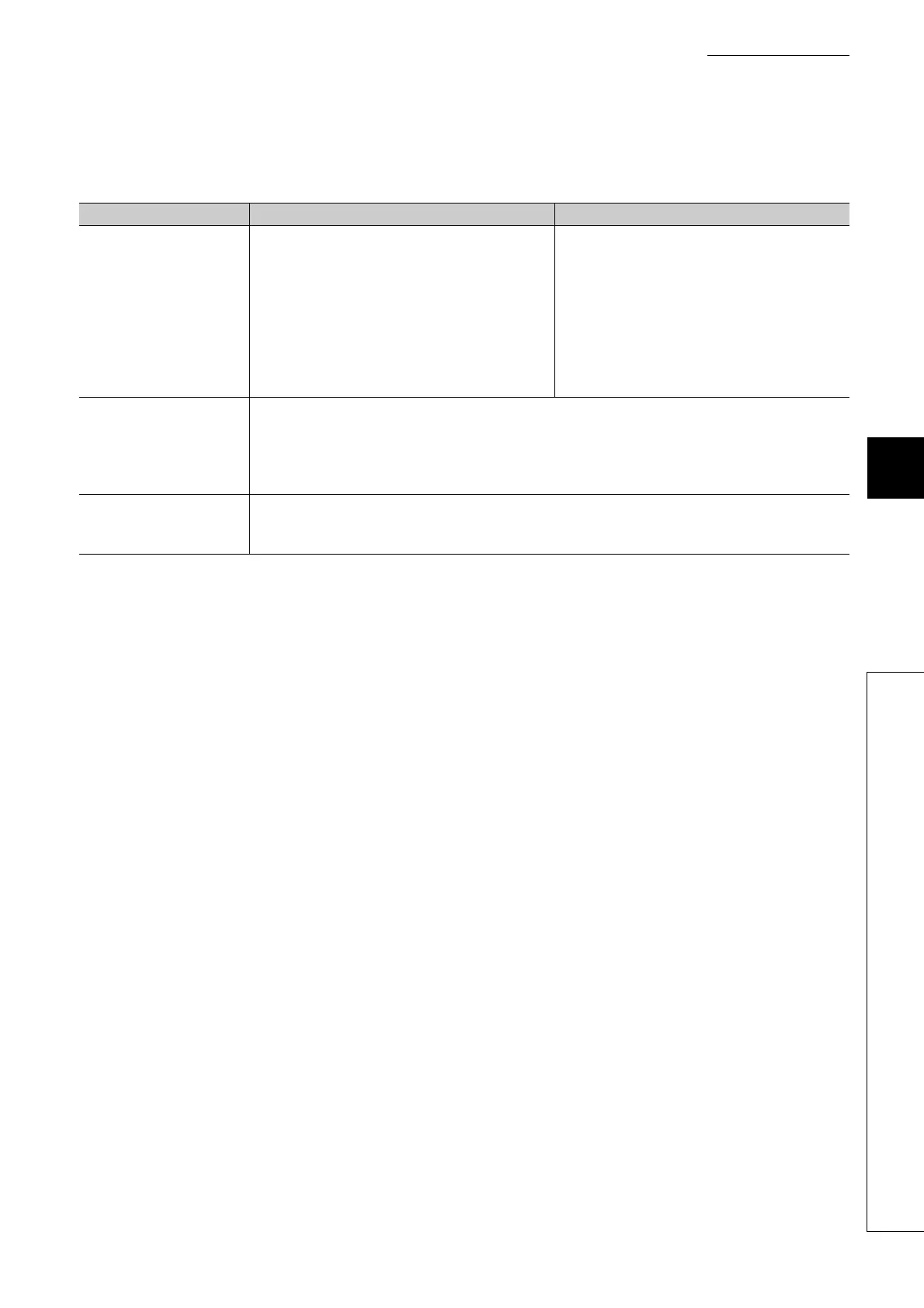
Table6.15 shows the external input/output forced on/off timing.
(f) Number of registerable devices
Forced on/off can be registered for 32 devices in total.
(g) When output Y contact is used in a sequence program
On/off operations in a sequence program are given priority.
(h) Checking forced on/off registration status
Forced on/off execution status can be checked by:
• reading the forced on/off registration status by GX Developer,
• flashing of the MODE LED (green), (The MODE LED flashes in green when at least one forced on/off is
registered.) or
• the on status of the 1st bit in SD840 (Debug function usage).
(i) Forcibly turning input or output on/off from multiple GX Developers
Forced on/off can be registered to a single CPU module from multiple GX Developers connected via network.
In this case, the last registration will be effective.
For this reason, the forced on/off status which is different from the status actually registered in the CPU module
may be displayed on the screen of GX Developer that registered forced on/off earlier.
When the forced on/off registration is performed from multiple GX Developers, click the "Update status" button
to update the registered data and execute the function.
Table6.15 Forced on/off timing
Refresh area Input Output
Input and output of modules
mounted on the base unit
• During END processing (input refresh)
• At execution of the COM instruction (input refresh)
• At execution of an instruction using direct access
input (DX) (LD, LDI, AND, ANI, OR, ORI, LDP, LDF,
ANDP, ANDF, ORP, ORF)
• At execution of the RFS or MTR instruction
• At execution of an instruction used for a system
interrupt (UDCNT1, UDCNT2, SPD)
• During END processing (output refresh)
• At execution of the COM instruction (output
refresh)
• At execution of an instruction using direct access
input (DX) (OUT, SET, DELTA, RST, PLS, PLF,
FF, MC, SFT)
• At execution of the RFS or MTR instruction
• At execution of an instruction used for a system
interrupt (PLSY, PWM)
Input and output of the CPU
module to be refreshed from
LX/LY of a CC-Link IE
Controller Network or
MELSECNET/H module
• During END processing (refresh via CC-Link IE Controller Network or MELSECNET/H)
• At execution of the COM instruction
• At execution of the ZCOM instruction
Input and output of the CPU
module to be refreshed from
RX/RY of a CC-Link module
• During END processing (auto refresh)
• At execution of the COM instruction (auto refresh)
• At execution of the ZCOM instruction (auto refresh)
 Loading...


