F940GOT Handy Series Installation 3
3-5
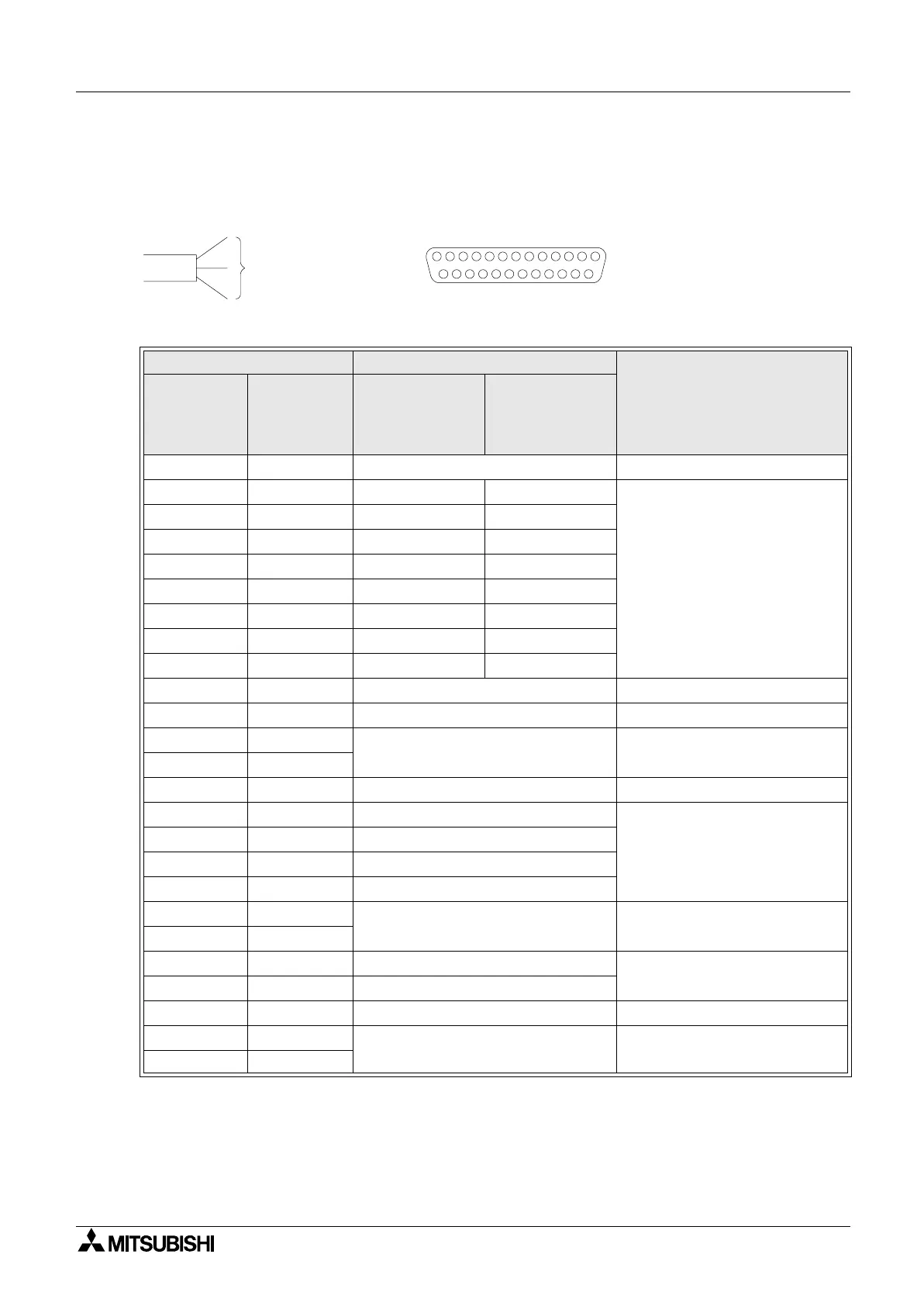
3.2.1 Signal Allocation of Connector and Untied Wires
The signal allocation within connector and untied wires of an external cable are shown below.
Note 1;
These are signals for communication with the PLC. When connecting to a port other than
the programming port of the FX, A, QnA or Q series PLC, refer to the manual of the
connected module. Also use a relay cable. For relay cable details, refer to section 1.3.2.
Table 3.1: Name of communication, lines, power supply and operation switches
External Cable Signal Name
Description
Pin No.
(F9GT-
HCAB-*M)
Color of
United wires
(F9GT-
HCAB1-*M)
F940GOT Handy
(RS-422)
F943GOT Handy
(RS-232C)
1 Drain wire FG (shield) Frame ground
2 Black TXD+ (SDA) SD (TXD)
Note 1
3 White TXD- (SDB) ER (DTR)
4 Red RTS+ (RSA) RD (RXD)
5 Green RTS- (RSB) DR (DSR)
6 Yellow RXD+ (RDA) RS (RTS)
7 Brown RXD- (RDB) CS (CTS)
8BlueCTS+ (CSA)NC
9 Gray CTS- (SCB) NC
10 Orange SG Signal ground
11 - NC Not used
12 Purple
DC 24V G 24V DC power supply “-”
13 Pink
14 Light green SW-COM COM for Operation switches
15 Sky blue SW1
Operation switches
16 Black/white SW2
17 Red/white SW3
18 Green/white SW4
19 -
NC Not used
20 -
21 Brown/white ES1
Emergency stop switch
22 Yellow/white ES1
23 - NC Not used
24 Blue/white
DC 24V + 24V DC power supply “+”
25 Gray/white
• • •
Distingushed
by color
United wires (20-core)
• • •
113
14
25
25-pin D-sub, male connector
 Loading...

