F940GOT Handy Series Installation 3
3-6
3.3 Installation of External Cable
Connect an optional external cable to the Handy GOT main unit.
*1 The cable cannot be used for the F943GOT Handy type (RS-232C communication type
Handy GOT).
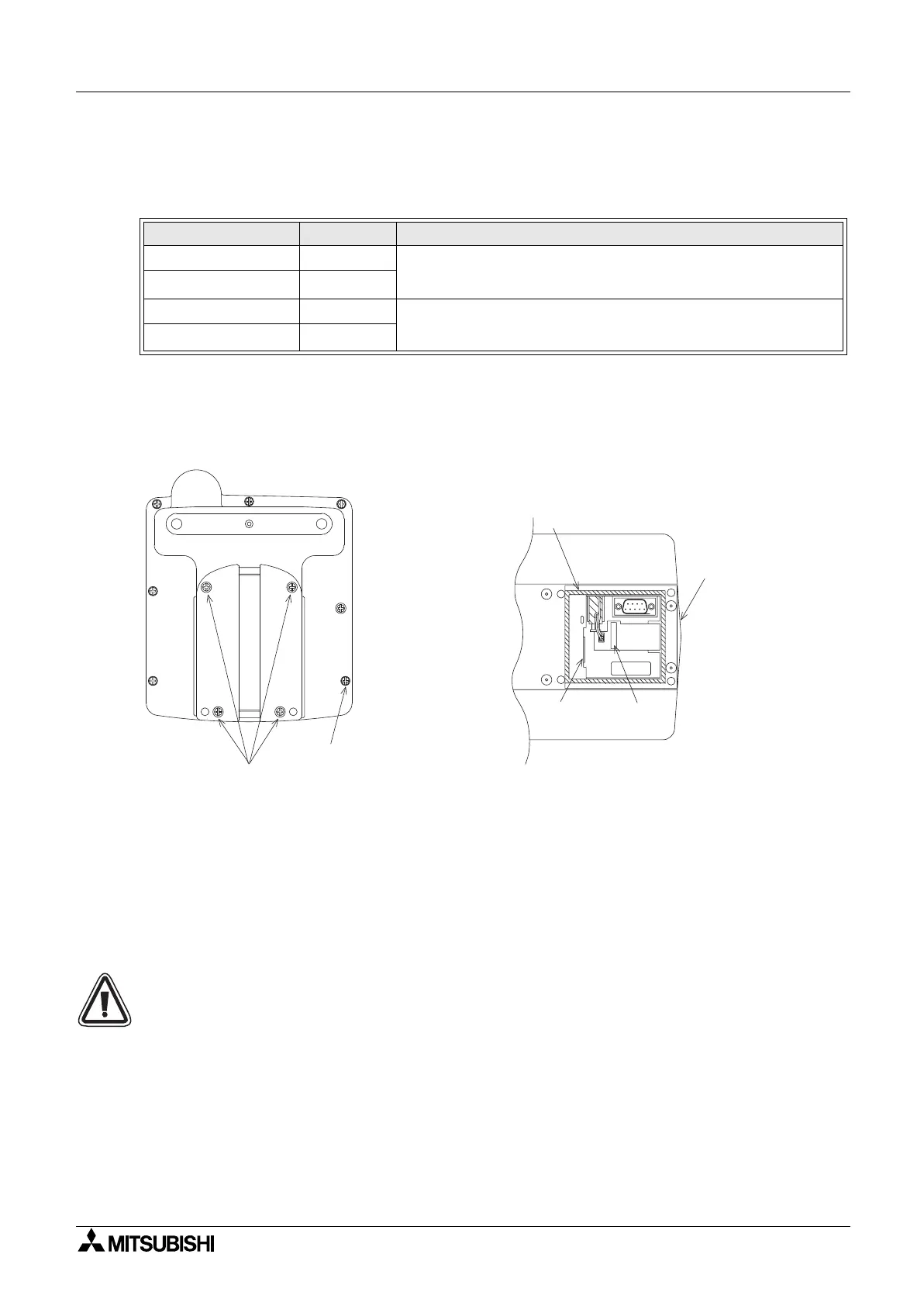
1) Remove the rear cover
Remove the mounting screws “a)”, and open the rear cover.
a) Rear cover mounting screws, (M3
×
8mm, 4 screws)
b) Packing seal
c) Mounting slot
d) Connector for communication or power switch (20-pin type)
e) Power connector (8-pin type)
Note:
• Never remove any screw (among seven screws located around the rear face of the
Handy GOT) other than the mounting screws “a)”.
If such a screw is removed, the waterproof ability may deteriorate or failure may occur.
• When installing the rear cover, securely the tighten mounting screws with a torque of
0.49 ~ 0.68 N
&
m. If tightened more than this, the rear cover may crack, and the water and
dustproof properties may be lost.
• Before closing the rear cover, make sure that the packing “b)” has not come off.
Table 3.2: External Cable
Model Name Length Description
F9GT-HCAB-3M 3m (9' 10")
25-pin D-sub connector on one side
F9GT-HCAB-10M
*1
10m (32' 9")
F9GT-HCAB1-3M 3m (32' 9")
Untied 20-core wires on one side
F9GT-HCAB1-10M
*1
10m (9' 10")
a)
Note
e)
d)
c)
b)
 Loading...

