pins,
and volumes
Reference.
Setting and Adjustment
1.1
Set switches, setting pins, and volumes
For the parts positions of the main panel and hinge panel
of the amplifier,
see the component layout (Appendix 5).
For the parts positions on the control circuit printed
circuit board, see the component layout (Appendix
6).
1.1.1
SF-CA card
(1) Dip switches
Switch
No.
Name
Description
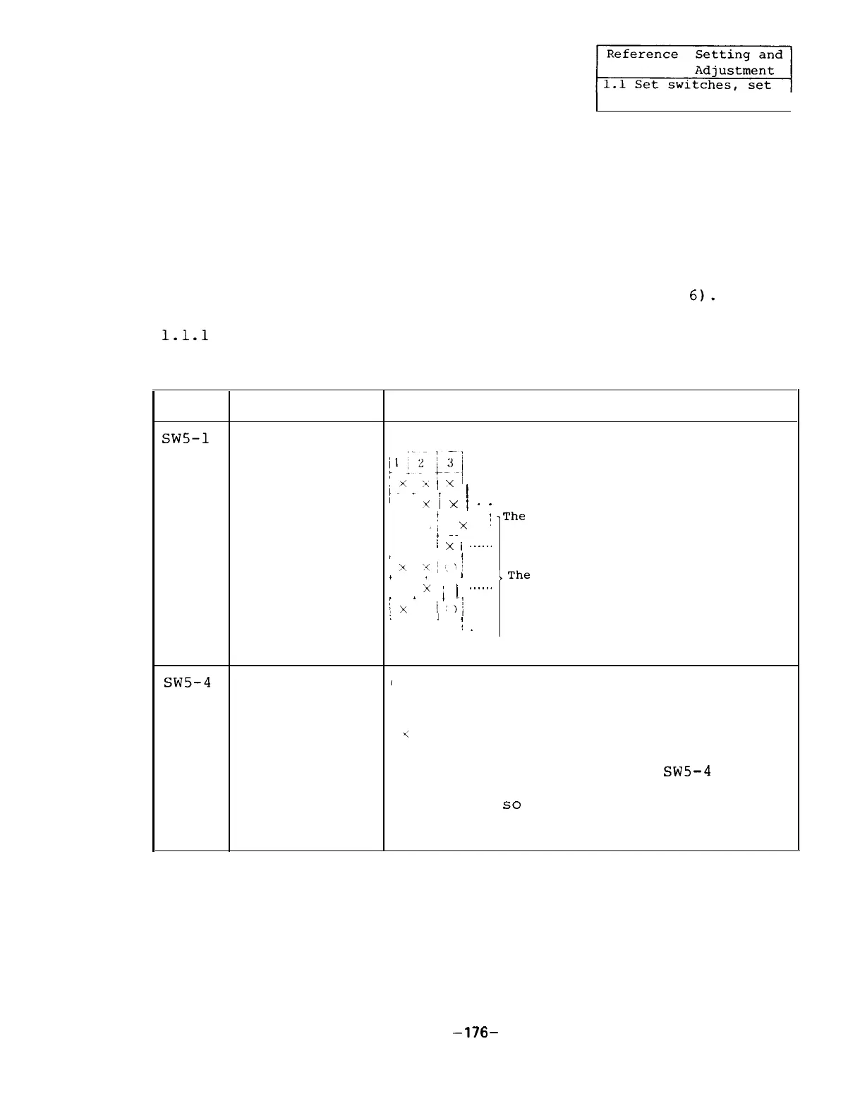
SW5-1
Test mode
Selects the test mode.
-3
selection
,
I
i-i
jq
i
T
.
‘“,
/
Y
y
i
x
/
.
.
Normal setting
Ignores the NC parameters-
!
X
,i
X
1
.
The
internal parameters become
valie.
+
~~
/
X
i
______
I
/
x
‘(~,‘/
/
/
1
,The
mode
x
1
1
......
(Normally,
this mode should)
r
.
;x
1:
1-1
not be set.
. . . . . .
:
1
,
/
.
sw5-4
Meter calibra-
I
tion
1
Meter full-scale output
<
Meter normal mode
Calibrates the full-scales of the speed
meter and load meter.
When
SW5-4
is
turned on,
the meter full-scale voltage
is output,
so
that the speed meter and
load meter are adjusted using VR4 and
VR5,
respectively.
: ON Position of dip switch.
:
OFF Position of dip switch.
-176-

 Loading...