1.3
Checking method and remedy of trouble classification B
1.3.1 When the power is turned on,
the display of the opera-
tion panel does not appear at all.
Item Cause
Check
Remedy
The AC power is not
D
Check the input pins Xl, X2,
o
Supply the power.
1
supplied.
and X3 of the amplifier using
a circuit tester.
The fuse
(Fl,
F2, and/or
0
Check that the indication
o
Replace the fuse
(Fl,
F2,
F3)
of the control power lamp LED1 on the SF-PW module
and/or
F3)
with a new one.
2
is blown.
lights.
(See Appendix
6(4)
.)
(See
Section 2.1.)
o
Check the electric continuity
using the circuit tester.
The power
(PSA,
PlSA,
0
Disconnect the connectors
o
Open the shortcircuited
por-
N15A,
or
P24)
outside
which are connected to the
tion of a circuit outside
the printed circuit outside of the SF-CA card in
the SF-CA card.
board SF-CA card is the order of
CONl,
CON3,
(See Appendix 1.2).
3
shortcircuited.
and so on by referencing
Appendixes 1-4 or 1-5, turn
on the power again, and then
check that the indication
lamp LED1 on the SF-PW module
lights.
The power supply inside
0
Disconnect the connectors
D
Replace the printed circuit
the printed circuit
which are connected between
board SF-CA card with a new
board SF-CA card is
the SF-CA card and SF-PW
one.
4
shortcircuited.
module (CON21 to
CON24),
turn (See Section
2.4.4)
on the power again, and check
that the indication lamp
LED1
lights.
The control power SF-PW
o
Check that 200 VAC power is
o
Replace the control power
module is defective.
supplied to the input
termi-
with a new one.
nals of the SF-PW module.
(See Section 2.4.1.)
0
Disconnect the connectors
5
(CON21 to
CON24),
turn on
the power again, and check
that the indication lamp
LED1 does not light.
(See Appendix
6(4).)
All the dip switches
o
Check the switch position of
o
Correctly set the dip
~~5-1
to
Sw5-4
on the
switch SW5 by referencing
switches
SWS-1
to SWS-4.
6
printed circuit board
Reference
1.1.1(l).
are not placed in the
(See Appendix
6(l))
OFF position.
-
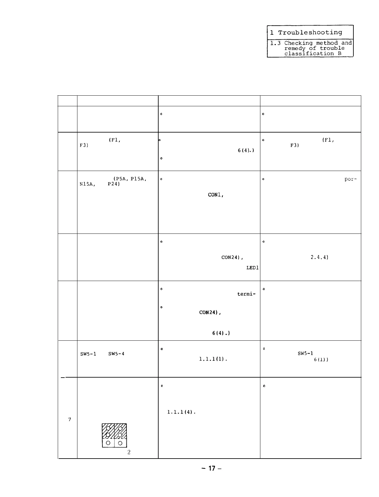
When the equipment is
0
Compare the positions of the
o
Correctly set the setting
not
linked with the NC
setting pins on the SF-CA
pins.
through the bus, the
card with those on the
setting pins PIN1 and attached setting pin list
PIN2 on the SF-CA card
by referencing Reference
are not placed as 1.1.1(4).
7
follows.
3
2
1
PIN I PIN
2
-
17-

 Loading...